The front suspension of the Gazelle car consists of a stamped I-beam connected to the steering knuckles using pivots
The pivots have a flat in the center and are locked in the holes of the beam with wedge stoppers.
Vertical loads from the steering knuckles are transferred to the beam by ball thrust bearings closed from dirt by rubber-metal caps.
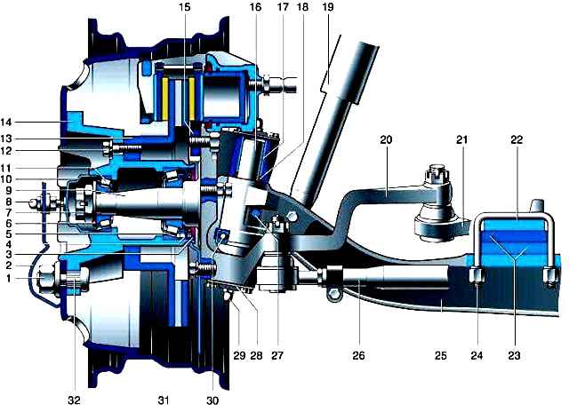
In the upper bosses of the steering knuckles, annular grooves are made, in which sealing rubber rings are installed, protecting the friction surfaces of the bushings and pivots from dirt.
The pivot holes in the bosses of the steering knuckles are closed with covers with gaskets.
To lubricate the pivot bushings, grease fittings are installed in the center of the covers.
The pivot bearings are lubricated at the same time as the lower bushings are lubricated.
Spiral grooves are made in the bushings of the steering knuckles for the passage of lubricant.
Replacement of the kingpins and parts of the kingpins can be found in the article - "Replacing the kingpin of a car."
The steering knuckles consist of two parts - a flange and a trunnion pressed into it.
The front wheel hubs are mounted on trunnions on two tapered roller bearings.
The tightening of the bearings is adjusted with a nut. The steering trapezoid is located behind the front axle beam.
The trapezoid arms are bolted to the steering knuckles.
Their threads during assembly are covered with a sealant that prevents them from unscrewing during operation.
The rotation angles of the steered wheels are limited by bolts screwed into the flanges of the steering knuckles.
Longitudinal steering rod is one-piece forged, transverse, tubular, with threaded tips.
The tips have a different thread direction, which allows you to adjust the toe-in without removing the tie rod from the car.
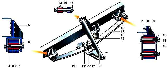
The suspension is made on longitudinal leaf springs with two hydraulic shock absorbers.
Suspension can use small or multi-leaf springs.
The leaf spring consists of two sheets, tightened with a clamp and a center bolt.
A multi-leaf spring has four leaves.
The spring is attached to the frame brackets through the ears formed by the bent ends of the sheets, while the front eyelet forms two sheets, and the back one only the upper (root) sheet.
The rear eye is attached to the spar through an earring that compensates for the change in the distance between the ends of the spring during suspension operation.
All movable connections: front and rear spring mounts, clevis mount, upper and lower shock absorber mounts are made on rubber bushings.
The spring is attached to the bridge beam with stepladders through the overlay. 4x4 vehicles have five leaf springs.
Replacement of springs can be found in the article - Replacing the front spring.
To limit the upward travel of the suspension, a rubber buffer is installed above the spring.
Shock absorbers are telescopic, two-pipe, collapsible.
The lower end (reservoir) is attached to the bridge beam, and the upper end (rod) to the frame spar bracket.
Replacement of shock absorbers can be found in the article - Replacing the shock absorbers of a Gazelle car.
Front suspension failures, causes and remedies
Moving the car to the side:
- Miscellaneous pressure Front Tire
Readjust tire pressure to normal
- A big difference in the caster angles of the kingpin on the right and left sides
Check for twisting of the front suspension beam or settlement of the front springs, wear of the pivot bushings
- Big difference in the camber angles of the left and right wheels
Check for beam deflection or wear on pivots and bushings.
Fix the beam if it is bent.
- Different tightening of the front wheel hub bearings
Check and adjust the tightness of the hub bearings
- Non-parallelism of the axes of the front and rear axles
Check the mutual position of the axles of the front and rear axles by measuring the distance between the centers of the wheels on the right and left sides.
If a difference is found, find the cause and fix it.
Wobbling of the front wheels:
- Wheel imbalance with complete tires
Replace or balance a wheel that is too unbalanced
- Increased wear in the steering rod joints
Replace worn hinges
Accelerated lateral tread wear:
- Wrong wheel alignment
Check if the tie rod or steering link arms are bent, and if there is any play in the tie rod joints.
Straighten bent parts, replace worn hinges.
Adjust wheel alignment.
Uneven tire tread wear:
- Large unbalance of the wheel with tire assembly
Change or balance a wheel
Knocks while moving
- Large kingpin axial play
Check the clearance between the upper knuckle boss and the beam boss.
Bring the gap up to 0.15mm, no more, by installing an adjusting steel gasket.
Replace the thrust bearing if necessary.
- Radial play of the kingpin in the bushings
Replace kingpin and bushings
- Insufficient tightening of the front wheel hub bearings or destruction of the bearings
Adjust the tightening of the bearings. Replace damaged bearings.
- Clearances in the conical joints of the tie rod pins
Tighten the pin nuts


