Diaphragm clutch
The car is equipped with a dry, single-disc, permanently engaged clutch with a hydraulically actuated release mechanism
The clutch consists of an aluminum crankcase, a release clutch with a bearing and a fork, a drive disk assembly (basket), a driven disk, a main and a working cylinder connected by a hose and a tube.
On vehicles equipped with ZMZ-406 and UMZ-4215 engines, only a diaphragm spring clutch is installed.
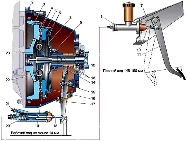
On vehicles with a ZMZ-402 engine, it is possible to install a clutch of both a diaphragm and a spring-lever type.
The driving disk (basket) consists of a casing in which a diaphragm spring, support rings and a pressure disk are installed.
A spring attached to the casing presses on the pressure plate with its edges.
The driven disc consists of a hub with a splined hole and two discs, one of which is riveted with leaf springs.
Friction pads are attached to them on both sides.
Curved leaf springs help to better fit the disc and additionally smooth out jerks in the transmission when the clutch is engaged.
For a smooth transmission of torque when starting the car or shifting gears, damper springs are installed in the disc windows.
The driven disc is pressed against the engine flywheel by the pressure plate of the basket.
Through friction linings that increase friction, the torque is transmitted to the driven disk and then to the input shaft of the gearbox, with which the driven disk is connected by a spline connection.
The clutch release actuator is used to temporarily disconnect the engine from the transmission.
When you press the clutch pedal, the clutch master cylinder piston moves forward.
The displaced liquid enters the working cylinder through the tube and hose, pushing the piston with the rod out of it.
The rod acts on the shank of the fork, which rotates on a ball joint, moving the clutch release clutch along the gearbox bearing cover with the other end.
The clutch bearing presses on the ends of the petals of the diaphragm spring.
Deforming, the spring ceases to act on the pressure plate, which in turn “releases” the driven one, and the transmission of torque stops.
Outside, the clutch mechanism is closed with an aluminum crankcase with a stamped steel pan (lower part of the crankcase) (ZMZ-402, UMZ-4215).
The crankcase is attached to the engine block with six bolts and two amplifiers.
On the other hand, four studs are screwed into the crankcase for securing the gearbox.
The crankcase has a seat for the clutch slave cylinder and a window for installing the fork.
To increase rigidity, an amplifier is installed on the lower part of the clutch housing of the ZMZ-406 engine.
Spring-lever clutch
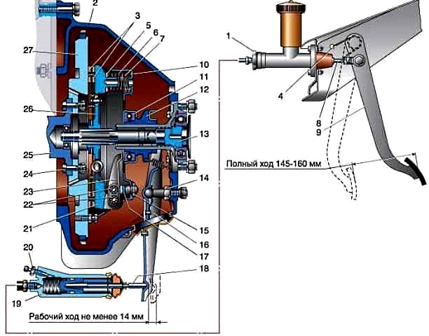
According to the principle of operation and design of most parts, a spring-lever clutch is similar to a diaphragm clutch.
The main difference is in the design of the drive disc (basket), which consists of a pressure plate casing, clutch release levers and pressure springs.
The design of the drive disc provides There is no transmission of torque through the clutch cover, as well as the centering of the pressure plate and its axial movement when the clutch is released.
The pressure plate is made with three protrusions, in the grooves of which the clutch release levers are installed on the axles.
The levers are connected to the clutch cover by support forks.
Spherical nuts are screwed onto the threaded parts of the forks.
The shanks of the support forks are punched to prevent loosening of the nuts.
Nuts are pressed against the spherical surfaces of the casing by conical springs.
The swivel mounting of the support forks compensates for the change in the distance along the radius between the axes of the levers when the clutch is disengaged, and also allows the ends of the levers to self-align.
The axles of the levers have needle bearings.
Three rectangular holes are made in the clutch cover for the projections of the pressure plate.
The casing is attached to the flywheel with six bolts.
There are nine pairs of cylindrical pressure springs under the casing.


