The tightness of the needle valve is checked on a stand that supplies fuel to the carburetor at a pressure of 30 kPa (3 m w.c.)
After setting the fuel level in the control tube of the bench, it must not fall for 10–15 seconds.
If the fuel level in the vial goes down, this indicates a fuel leak through the needle valve.
In case of fuel leakage, replace the needle valve.
Setting the fuel level in the float chamber
The fuel level necessary for the normal operation of the carburetor is ensured by the correct installation of serviceable elements of the locking device.
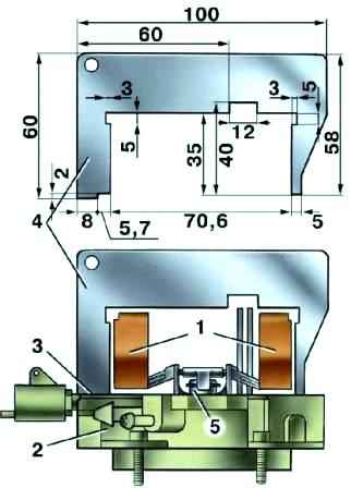
Check the correct installation of the float 1 (Fig. 1) with a gauge 4, for which set it perpendicular to the cover 2, which is held horizontally with the floats up.
There must be a gap of no more than 1 mm between the gauge along the contour and the floats.
Adjust if necessary by bending the tongue and float arms.
The bearing surface of the tongue must be perpendicular to the axis of the needle valve 5 and must not have dents and nicks
Carburettor drive adjustment
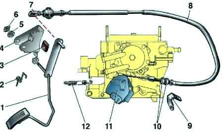
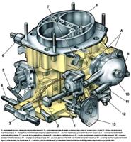
When the throttle control pedal 1 (see Fig. 2) is fully depressed, the throttle valve of the second chamber should be fully open and sector 11 should not have additional travel.
When the pedal is released, the throttle valves of both chambers should be fully closed.
If not, adjust the position of the pedal and throttle with the adjusting nuts 10 on the front end of the drive cable.
Checking the operation of the semi-automatic carburetor launcher
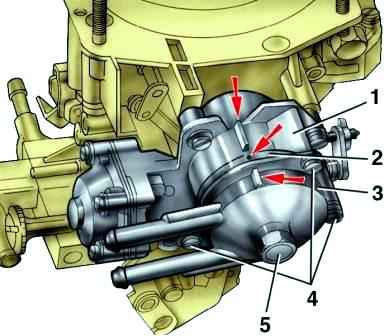
Check the correct installation of the bimetallic spring of the starting device, for which visually determine the alignment of three marks (marks are shown by arrows in Fig. 3): on body 1 of the starting device, body 2 of the bimetallic spring and body 3 of the liquid chamber.
If the marks do not match, loosen the screws 4 securing the case 2, turn it until it aligns with the mark on the case 1 and tighten the screws.
Loosen bolt 5, turn housing 3 until the marks align and fasten the bolt.
Start a cold (coolant temperature 15–25°C) engine and check the engine speed after 15–20 seconds, which should be (2400±200) min -1 ..
If the speed does not match this, adjust the starting gap B at the throttle valve of the first chamber to a value of (1.1 ± 0.05) mm.
Starting gap adjustments
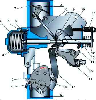
Adjust on a cold engine, when the air damper is covered by the starter.
Remove the air filter and check the starting gap A (fig. 4) of the air damper 7.
If gap A does not correspond to the value (2.5 ± 0.2 mm), remove the stopper of the adjusting screw 11 and adjust this gap with this screw.
Adjusting the starting gap B at the throttle valve of the first chamber must be performed on the removed carburetor.
Close throttle 1 of the first chamber.
Turn the cam 10 counterclockwise with a screwdriver and set the lever stop 14 to the largest step along the radius.
Using screw 15, adjust clearance B at the throttle valve, equal to (1.1 ± 0.05) mm.
Install the removed components and parts, start the engine, check, 15–20 seconds after starting, the crankshaft speed of the cold engine, which should be equal to 2400 ± 200 min -1 .
The idle speed of a warm engine should be 750–800 min -1 .
Engine idle adjustment
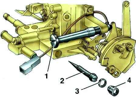
The adjustment is provided by adjusting screw 2 (Fig. 5) of the quality (composition) of the mixture and adjusting screw 1 of the amount of the mixture.
Adjusting screw 2 is closed with a plug 4. To access the screw, remove the plug with a corkscrew.
Idling adjustment must be carried out on a warm engine (coolant temperature 90–95 ° C), with adjusted gaps in the gas distribution mechanism, with a correctly adjusted ignition timing.
Using the adjusting screw 1 of the mixture amount, set the engine crankshaft speed within 750–800 min -1 using the stand tachometer.
Using the adjusting screw 2 of the quality (composition) of the mixture, achieve the content of carbon monoxide (CO) in the exhaust gases within (1 ± 0.3)% at this position of the screw 1 [CO content is reduced to 20 ° C and 101.3 kPa ( 760 mmHg)].
At the end of the adjustment, sharply press the throttle pedal and release it, the engine should increase the crankshaft speed without interruption, and when it decreases, it should not stall.
If the engine is stopped with screw 1, increase the crankshaft speed within 750–800 min -1 .
Insert a new plastic plug 4 into the hole for adjusting screw 2 of the mixture quality.


