")
")
")
")
")
")
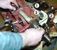
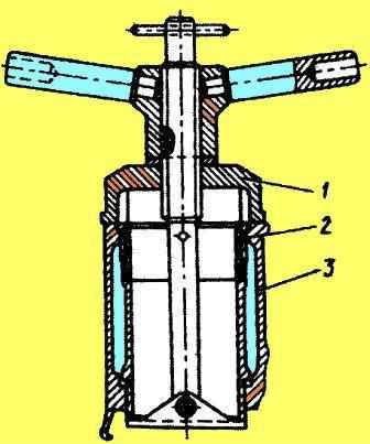
To replace the sleeves, you need to use a puller or make it in accordance with the picture
Cylinder liners and the seating surfaces of the cylinder block under the liners should be wiped with a napkin and blown with compressed air.
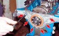
Install the cylinder liners in the diesel block.
The protrusion of the cylinder liner flanges above the plane of the block when the liner is pressed with a force of 9 ± 0.1 kN should be 0.05 ... 0.11 mm.
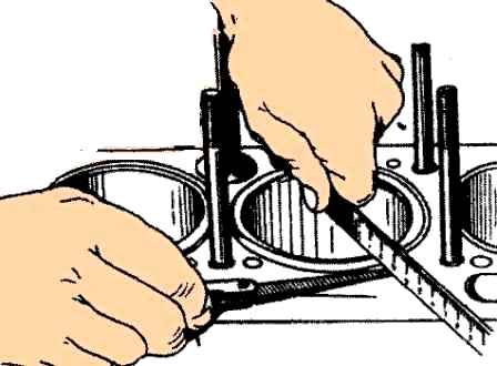
The protrusion of the sleeves can be checked with tool I 806.01020.
You can also check with a metal ruler and a probe.
Before installation in the block, the rubber o-rings and the lead-in of the sleeve must be lubricated with engine oil M10G2 GOST 8583-78.
When installing cylinder liners in the block, cutting rubber sealing rings is not allowed.
After installing the cylinder liners and tightening the bolts (nuts) for fastening the technological heads, the block must be checked for leaks with water at a pressure of 0.6 MPa for 1 minute.
Water leakage and dripping are not allowed.
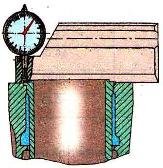
The non-roundness of the inner surface of the cylinder liners after installing them in the block and tightening the bolts of the technological head should not exceed 0.04 mm at a length of 100 mm from the lower end of the sleeve and 15 mm from the top.
Maximum sleeve pressing force - no more than 3000 N.
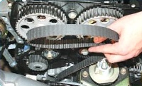
The camshaft with gear must be installed taking into account the maximum axial movement - no more than 0.25 mm.
The block head gasket must be installed with the wide side of the edging towards the block.
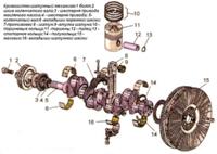
Cylinder liners according to the inside diameter and pistons according to the outside diameter of the skirt are sorted into three size groups.
The designation of groups (B, C, M) is applied on the upper collar of the sleeve and on the piston head.
The dimensions of the inner surface of the sleeve by size groups are shown in the table.
Dimensional groups of pistons and cylinder liners
|
Designation dimensional groups
|
Diameter skirts piston, mm |
Diameter sleeves cylinder, mm |
Gap between piston and a sleeve, mm |
|---|---|---|---|
|
B |
110-0.05-0.07 |
110+0.06+0.04 |
0.09…0.13 |
|
C |
110-0.07-0.09 |
110+0.04+0.02 |
0.09…0.13 |
|
M |
110-0.09-0.11 |
110+0.02 |
0.09…0.13 |
It is allowed to install sleeves with an oversize of 110.7 mm.
In this case, the gap between the sleeve and the piston of the repair size of 0.09-0.13 mm must be ensured by selective selection.