")
")
")
")
")
")
Scheme of the diesel liquid cooling system with forced circulation of the coolant from the centrifugal pump is shown in Figure 1
The temperature of the coolant in the system is controlled by a temperature gauge, the sensor of which is installed at the rear of the cylinder head.
In addition, an emergency coolant overheat sensor is installed in the liquid pump body
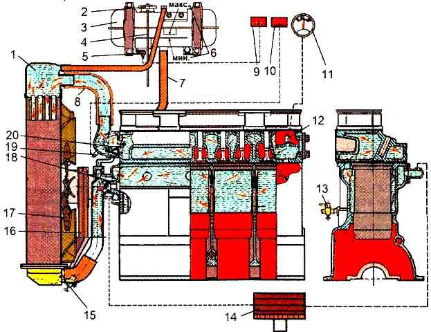
On cars of the latest construction series, instead of a liquid level control valve, a coolant level control indicator sensor 5 is installed in the expansion tank.
It is forbidden to operate a diesel engine when the warning light for emergency overheating of the coolant is on.
The temperature of the coolant in the cooling system must be maintained within 75°-95°C.
When opening the plug of the expansion tank when the engine overheats, it should be remembered that steam can be ejected from the neck of the tank, leading to burns to the face and hands.
A thermostat with a solid filler is used to accelerate the warm-up of the diesel engine after start-up and automatically control the temperature regime at various loads and ambient temperatures.
The fluid pump, fan and generator are driven by the diesel crankshaft pulley using two V-belts.
Litol-24 grease is put into the bearing cavity of the pump housing when the pump is assembled at the factory and does not require replenishment during the entire period of operation of the diesel engine.
Greasing should only be done after the fluid pump has been dismantled.
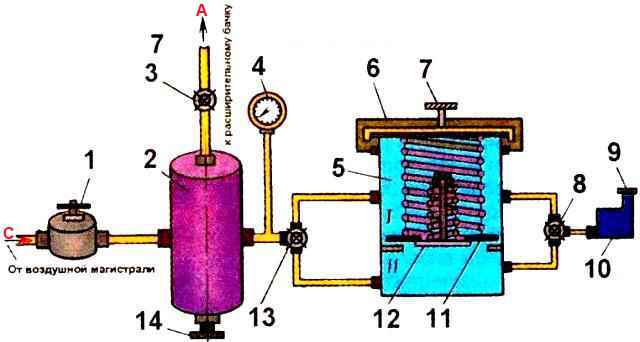
Checking the tightness of the diesel cooling system and the condition of the radiator cap valves using the DSO-2 indicator (Fig. 2).
A float is placed in the body of the device, with the help of which the moment of operation of the expansion tank plug valves, adjusted to a certain pressure, is fixed.
When valves 3, 13 are closed, pressure is created in the air cylinder. With the help of a reducer, it is set to 0.15-0.16 MPa.
The plug removed from the neck of the expansion tank is fixed on glass 5.
When valve 8 is closed, air is supplied to the upper cavity of the glass.
The lower cavity of the glass is connected to the indicator using a tap 8. The pressure acting on the steam valve is fixed by a pressure gauge at the moment the float rises in the indicator.
Then, the indicator is connected to the lower cavity of the glass, and air is supplied from the air cylinder to the upper cavity and the pressure at which the air valve of the plug opens is fixed.
To check the tightness of the cooling system with the DSO-2 device, it is necessary to install the nozzle of the device connected to the tap 3 instead of the plug on the neck of the expansion tank.
When valves 3 and 13 are closed, the reducer creates a pressure of 0.6-0.7 MPa and opens valve 3.
The change in pressure in the cooling system is monitored using a stopwatch and pressure gauge.
At the same time as checking the tightness of the system, you can check the condition of the cylinder head gasket on a running diesel engine.
For this check, set the minimum speed of the crankshaft and observe the readings of the pressure gauge.
The fluctuation of the pressure gauge needle indicates the flow of gases from the cylinders into the cooling system, i.e. about damage to the gasket or the cylinder head itself.