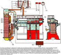
VAZ-21114 engine cooling system - liquid, closed type, with forced circulation
Consists of an engine cooling jacket, a radiator with an electric fan, a thermostat, a pump, an expansion tank and connecting hoses
The pump circulates the coolant through the cooling jacket of the block and cylinder head, after which the liquid passes through the thermostat into the radiator, where it gives off heat to the cooling air
The movement of fluid through the cooling jacket and the radiator forms a large circulation circle, and the movement of fluid through the engine cooling jacket, bypassing the radiator, forms a small circulation circle.
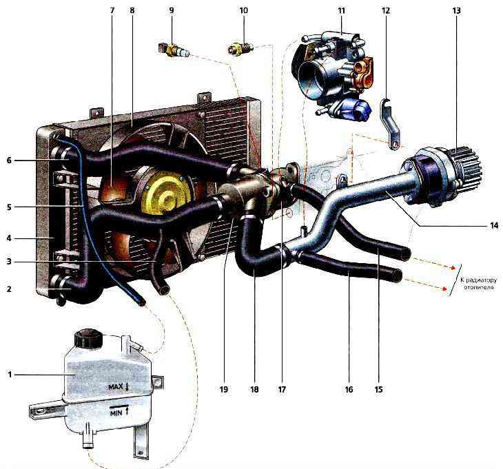
Cooling system: 1 - expansion tank; 2 - radiator outlet hose; 3 - inlet hose, 4 - radiator; 5 - outlet hose; 6 - radiator inlet hose; 7 - electric fan; 8 - casing of the electric fan; 9 - coolant temperature sensor; 10 - coolant temperature indicator sensor; 11 - throttle assembly; 12 - bracket for the coolant pump pipe; 13 - coolant pump; 14 - coolant pump pipe; 15 - inlet hose of the heater radiator; 16 - outlet hose of the heater radiator; 17 - outlet pipe; 18 - coolant pump pipe hose; 19 - thermostat housing
The cooling system also includes a heater radiator and a throttle assembly heating unit.
The liquid circulates through them constantly and does not depend on the position of the thermostat valves.
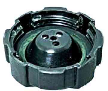
The tightness of the system is ensured by an inlet and outlet valve located in the cover of the expansion tank.
The exhaust valve maintains an increased pressure in the system on a hot engine, due to this, the boiling point of the liquid becomes higher, and steam losses are reduced.
It starts to open at a pressure of at least 1.1 bar.
The inlet valve opens when the pressure in the system drops by 0.03-0.13 bar relative to atmospheric pressure (on a cooling engine).
The thermal mode of the engine is maintained by a thermostat and an electric radiator fan.
The electric fan is switched on through the relay at the signal of the controller.
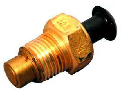
To monitor the temperature of the coolant, a sensor is screwed into the engine cylinder head, connected to the temperature gauge in the instrument cluster.
In the outlet pipe, next to the thermostat housing, there is a coolant temperature sensor that provides information to the controller.
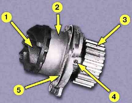
The coolant pump is a vane, centrifugal type, driven from the crankshaft pulley by a timing belt.
The pump body is aluminum. The roller rotates in a double-row bearing.
The bearing is greased for life.
The outer ring of the bearing is locked with a screw.
A toothed pulley is pressed onto the front end of the roller, an impeller is pressed onto the rear end.
A thrust ring made of a graphite-containing composition is pressed against the end of the impeller, behind which there is an oil seal.
The pump housing has an inspection hole to detect fluid leakage when the pump fails. It is recommended to replace the pump as an assembly.
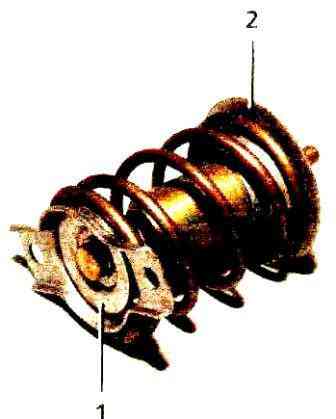
The thermostat controls the redistribution of fluid flows.
The thermostat has a solid temperature sensing element and two valves that redistribute coolant flows.
On a cold engine, the main thermostat valve shuts off the fluid flow from the radiator, and the fluid circulates only in a small circle, bypassing the radiator.
At a temperature of (85 ± 2) ° C, the thermostat valves begin to move, passing the flow of liquid into the radiator and blocking the bypass sleepy channel.
At a temperature of about (100 ± 2) °С, the main valve opens completely, and the bypass valve closes.
Almost all fluid circulates in a large circle through the engine radiator.
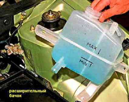
Coolant is poured into the system through the expansion tank.
It is made of translucent polyethylene, which allows you to visually control the liquid level. To do this, the labels "MAX" and "MIN" are marked on the wall of the tank.
In the upper part of the tank there is a branch pipe for connection with the radiator steam outlet hose, in the lower part there is a branch pipe for connection with the inlet hose.
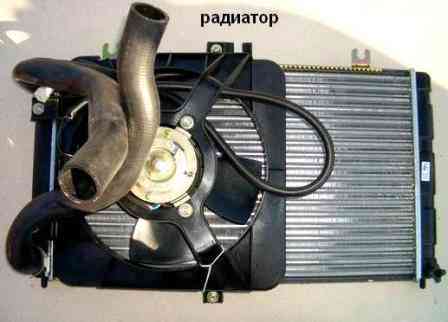
The radiator consists of two vertical plastic tanks (the left one with a baffle) and two horizontal rows of round aluminum tubes passing through the cooling plates.
The tubes are connected to the tanks through a rubber gasket. The liquid is supplied through the upper pipe, and discharged through the lower one.
There is a thin steam outlet hose next to the inlet. A shroud with an electric fan is installed on the radiator.
There is a drain plug at the bottom of the right tank.
The use of water in the cooling system is not recommended: hot water causes intense corrosion of aluminum parts.


