")
")
")
")
")
")
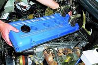
Cylinder head common to four cylinders, cast aluminum alloy, with tent-shaped combustion chambers
Inlet and outlet channels are displayed on different sides of the block head
The valves are arranged in a V - figuratively in two rows: inlet on one side, outlet on the other.
Sintered valve seats and brass valve guides are pressed into the head.
The inner diameter of the guide bushings is 7 ± 0.015 mm, the outer diameter (for bushings supplied as spare parts) is 12.079-12.090 mm and 12.279-12.290 mm (the bushing is increased by 0.2 mm).
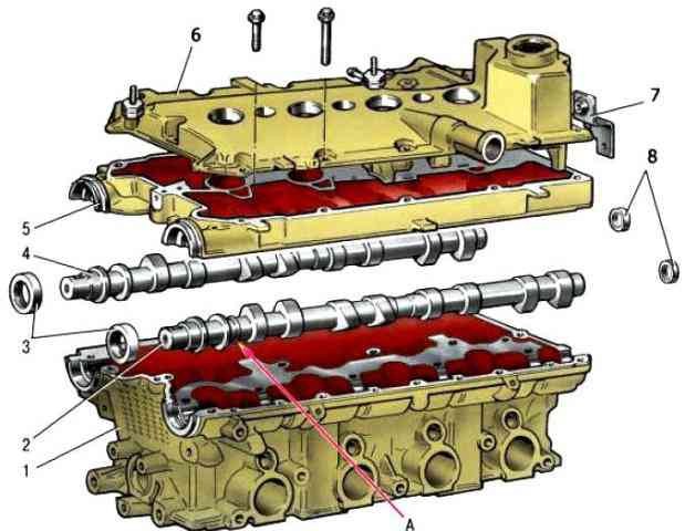
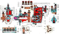
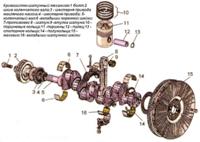
Details of the cylinder head: 1 - head of the block; 2 - intake camshaft, 3 - oil seal; 4 - final camshaft; 5 camshaft bearing housing; 6 - block head cover, 7 - bracket for fastening the wiring harness; 8 - plugs; A - distinctive belt of the intake camshaft
The diameter of the inlet valve plate is 29 mm, the exhaust valve is 25.5 mm.
The diameter of the inlet valve stem is 6.975±0.007 mm, the exhaust valve is 6.965±0.007 mm.
One spring is installed for each valve.
The length of the spring in the free state is 38.19 mm, under load 240 ± 9.6 N (24.5 ± 0.98 kgf) should be 32 mm, and under load 550 ± 27.5 N (56.1 ± 2.8 kgf) - 24 mm.
The valves are actuated by camshaft cams through cylindrical hydraulic pushers located in the guide holes of the cylinder head along the axis of the valve holes.
The hydraulic tappets automatically eliminate the clearance in the valve mechanism, so it is not necessary to check and adjust the clearance in the valve mechanism during maintenance of the car.
The oil for the operation of the hydraulic pushers is supplied from the lubrication system through a vertical channel in the cylinder block to a channel in the cylinder head near the 5th mounting bolt, and then through the upper channels made on the lower plane of the bearing housing.
Oil is also supplied through the same ropes to lubricate the camshaft journals.
In the vertical channel of the cylinder head there is a check ball valve that prevents oil from draining from the upper channels after the engine is stopped.
The valves are driven by two camshafts: intake and exhaust.
The shafts are cast iron and equipped with five bearing journals that rotate in sockets made in the cylinder head and in one common camshaft bearing housing.
To increase wear resistance, the working surfaces of the cams and the neck for the stuffing box are bleached.
In order to distinguish the intake camshaft from the exhaust camshaft, a distinctive band A is made on the intake shaft near the first bearing.
The shafts are kept from axial movements by thrust collars located on both sides of the front support.
The front ends of the camshafts are sealed with self-tightening rubber seals.
The rear holes located along the axis of the shafts in the cylinder head and bearing housing are closed with rubberized cap plugs.