")
")
")
")
")
")
After dismantling, we install the engine on a stand for disassembly
Remove the generator, cylinder head, flywheel, oil filter
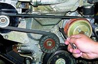
With a 17 spanner wrench, we unscrew two bolts 1 of the lower fastening, and with a 13 wrench, bolt 2 of the upper fastening of the bracket of the front right support of the power unit.

Remove the bracket

With a 13 head, we unscrew the three bolts securing the generator bracket.

Remove the generator bracket.
Remove the engine oil pan
Remove the oil receiver (see Removing the oil receiver) and the oil pump (see Removing and disassembling the oil pump).
Having unscrewed the two bolts securing the supply pipe of the coolant pump to the cylinder block with a 10 key, remove the pipe and its sealing gasket.

With a head of 10, we unscrew the six bolts securing the gland holder

Remove the rear oil seal holder

The connection between the oil seal holder and the cylinder block is sealed with a gasket

With a head of 14, we unscrew the two nuts of the bolts securing the connecting rod cover (the connecting rod must be at BDC)

By tapping the sides of the connecting rod cap with a plastic (or soft metal) hammer

Remove the connecting rod cover

Remove the connecting rod bearing shell from the cover

Resting the wooden handle of the hammer against the ends of the rods of the connecting rod bolts, we shift the lower head of the connecting rod from the crankshaft neck

Remove the piston with the connecting rod from the cylinder.
Remove the connecting rod bearing shell from the lower head of the connecting rod.
Similarly, we remove pistons with connecting rods from other cylinders.
If the parts of the connecting rod and piston group are not damaged and slightly worn, they can be reused.
Therefore, when disassembling, you need to mark the parts so that they can be installed in their places during subsequent assembly.

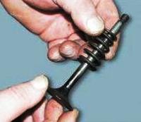
With your fingers, carefully (without much effort) open the lock of the upper compression ring

Remove the ring from the piston groove. Remove the lower compression ring in the same way.

Opening the lock, remove the oil scraper ring

Remove the oil scraper ring expander.
To remove the piston from the connecting rod, pry off the piston pin circlip with a screwdriver and remove it from the annular groove of the piston boss.

Remove the other piston pin circlip in the same way

Push out the piston pin with a mandrel and remove the piston from the upper head of the connecting rod

We also remove the rest of the pistons

Using a 17 head, we unscrew the two bolts securing the crankshaft main bearing cap.

Remove the main bearing cap.

Remove the lower crankshaft main bearing shell from the cover.
In the same way, remove four more crankshaft main bearing caps.

We remove the crankshaft from the cylinder block and then remove the two thrust half rings of the crankshaft (shown by arrows) from the grooves of the third main bearing support (in the cylinder block).

Remove the upper crankshaft main bearing shells from the cylinder block supports.

Using a sharp tool, remove the remaining sealant from the mating plane of the cylinder block under the oil pan
Remove the remnants of the cylinder head gasket.

We clean the mating surfaces of the cylinder block under the coolant pump pipe and the crankshaft rear oil seal holder.
After disassembling the engine, we thoroughly wash and clean the parts of the cylinder-piston group from carbon deposits to check their technical condition.

To determine the wear of the cylinder with a bore gauge, we measure the cylinder diameter in four zones (at a distance of 8, 15, 50, and 90 mm from the upper plane of the cylinder block) and in two directions (parallel and perpendicular to the axis of the crankshaft).
In the area of the first belt (up to 8 mm), the cylinder practically does not wear out. Therefore, according to the difference in measurements in the first and other belts, you can determine the wear of the cylinder.
If the wear of the cylinders exceeds 0.15 mm, it is necessary to bore and honing the cylinders to a repair (increased by 0.4 or 0.8 mm) size.
To determine the wear of the piston skirt with a micrometer, we measure its diameter in a plane perpendicular to the axis of the piston pin, at a distance of 55 mm from the piston bottom

With a micrometer we measure the diameters of all main and connecting rod journals of the crankshaft in two diametrically opposite planes.
We grind the crankshaft journals to the nearest repair size if the wear or ovality is greater than 0.03 mm, and also if there are scratches and marks on the journals.

After grinding the crankshaft journals, the oil channel plugs must be removed.
Then we thoroughly rinse and blow the channels with compressed air to remove abrasive residues.
Grinding the crankshaft journals, removing and installing plugs.
We assemble the engine in reverse order.
We install new crankshaft main bearing shells of nominal or repair size (after grinding the shaft journals).
Inserts with a groove on the working surface are installed in the cylinder block supports, and without grooves - in the main bearing caps.
Lubricate the liners with engine oil and place the crankshaft in the cylinder block supports.

We insert thrust half rings lubricated with engine oil into the grooves of the third main bearing support.
The surfaces of the semi-rings with an anti-friction coating (grooves are made on them) must face the thrust surfaces of the crankshaft.

We install the main bearing caps in accordance with the marks printed on their outer surface (the caps are counted from the timing belt drive side).
When installing, orient the covers so that their marks are located closer to the front side of the cylinder block (generator mounting side).
In this case, the locks of the upper and lower shells of each main bearing are located on the same side.
We tighten the bolts of the main bearing caps with a torque of 68 - 84 Nm.
Pistons for cylinders are selected according to the diameter classes of the cylinder and piston skirts.

The diameter class of each cylinder (denoted in our case by the letter "C") is stamped opposite the cylinder on the lower plane of the block (the plane of the oil pan attachment).

The piston skirt class is marked on the piston head. Pistons of the same mass class are installed on the engine.
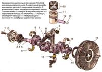
Marking on the piston crown:
- - d– piston class according to the diameter of the pin hole;
- - C – class of piston skirt diameter;
- - ↓ - when installing the piston in the cylinder, the arrow should be directed towards the timing drive;
- - Г - piston mass class.

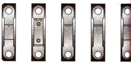
The marking of the connecting rod classes by mass and diameter of the hole for the piston pin is applied on the connecting rod cap.
Marking on connecting rod cap:
- - H – connecting rod weight class;
- - 2 - connecting rod class according to the diameter of the hole for the piston pin.

Before assembling the connecting rod and piston group from new parts, it is necessary to pick up the fingers to the pistons and connecting rods.
The class of the piston and connecting rod in terms of the diameter of the holes for the pin must correspond to the class of the diameter of the pin.
A properly selected piston pin, lubricated with engine oil, should enter the hole in the upper connecting rod head with thumb pressure and not fall out of it in a vertical position.
When assembling the piston with the connecting rod, we orient them so that when installed in the cylinder, the serial number stamped on the connecting rod is located closer to the rear wall of the cylinder block (on which the oil filter is located).
Before installing the piston rings on the piston, it is necessary to check the thermal gaps in the locks of the rings.

To do this, insert the piston ring into the cylinder in which it will be installed during assembly and align the ring with the piston head.

We check the gap in the piston ring lock with a set of flat feelers.
The gap should be 0.25 - 0.45 mm. The maximum allowable wear clearance is 1 mm.
Lubricate the grooves on the pistons under the piston rings with engine oil. We install the rings on the pistons.

Set the lower compression ring with the groove ("scraper") down.
If the ring is marked "TOP" or "TOP", the ring is placed with the mark up. Arrange the rings as follows:
- - we orient the lock of the upper compression ring at an angle of about 45˚ to the axis of the piston pin;
- -l ock of the lower compression ring—at an angle of 180˚ to the axis of the lock of the upper ring;
- - oil scraper ring lock - at an angle of 90˚ to the axis of the upper compression ring lock.
When installing the oil scraper ring, we place the expander joint on the side opposite to the ring lock.

Before installing the piston into the cylinder, we put an adjustable mandrel on the piston and, by tightening the mandrel, compress the piston rings.
Install the piston with the connecting rod in the cylinder. In this case, the connecting rod journal of the crankshaft of this cylinder must be in the BDC position.

Resting the hammer handle against the bottom of the piston, we push it into the cylinder.
Having removed the mandrel, we send the piston into the cylinder with the hammer handle until it stops.
At the same time, we control the fit of the connecting rod lower head bushing on the crankshaft journal.

When installing the connecting rod cover, the serial numbers on the connecting rod and the cover must match and be located on the same side of the connecting rod
Further assembly of the engine is carried out in reverse order.