")
")
")
")
")
")
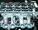
The gas distribution mechanism consists of a camshaft, intake and exhaust valves, as well as parts for their installation and drive: pushers, rods, rocker arms, adjusting screws with nuts, plates with crackers, springs, racks and rocker axles
Pushers - steel, have spherical bottoms.
As a result of the fact that the camshaft cams are made with a slight inclination, the pushers perform a rotational movement during operation.
The push rods are made of steel bar.
The spherical part inside the pusher and the rod cup are hardened.
The rocker arms are made of steel and swing on an axle mounted on four posts.
Extreme posts - increased rigidity.
The axis of the rocker arms is hollow; has eight radial holes for rocker lubrication.
The movement of the rocker arms along the axis is limited by spacer springs.
The inlet and outlet valves are made of heat resistant steel. They move in guide bushings pressed into the cylinder head.
Each valve closes under the action of two springs, external and internal, which act on the valve through the plate and crackers.
Sealing cuffs installed on the valve guide bushings prevent oil from entering the diesel cylinders through the gaps between the valve stems and the valve guide bushings.
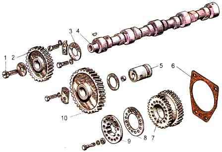
The working surfaces of the bearing journals and camshaft cams must be clean, free of nicks and scratches.
The height of the camshaft cams should be 41.32±0.05 mm.

The surfaces of the cams must be machined into a cone (Fig. 2).
The larger base of the cone should be on the side of the camshaft gear.
The diameters of the camshaft journals must be at least 49.88 mm (for a new shaft - 50-0.050 mm).
The out-of-roundness and tolerance of the profile of the longitudinal section of each camshaft journal is 0.01 mm.
The oil passages of the camshaft must be clean, free of tarry deposits.
The channels must be thoroughly flushed and blown out with compressed air.
The gear must be pressed onto the camshaft until it stops.
The bolt of the gear to the camshaft must be tightened to a torque of 110-160 Nm.
The gap between the end face of the neck of the assembled camshaft and the thrust flange (axial play of the shaft) is allowed within 0.3-1.04 mm (see Fig. 2).
The bushing must be pressed into the intermediate gear flush with the ends.
The surfaces of the ends of the gear and bushing must be clean, without dents.
The roughness of the treated surfaces is Ra≤2.5 µm.
The inner surface of the intermediate gear bushing must be clean, free of scratches and scuffs.
The roughness of the machined surface is Ra≤2.5 µm.
The out-of-roundness and tolerance of the profile of the longitudinal section of the inner surface of the intermediate gear bushing is 0.008 mm.
The spline flange of the fuel pump drive gear must freely, without jamming, enter the splines of the pump shaft bushing.
The replacement bushing of the fuel pump drive gear should be pressed in from the side of the short hub until the bushing stops against the end face of the gear hub.
When adjusting the gap between the end of the adjusting bolt and the surface of the bar, the adjusting bolt should be screwed into the bar until it stops, then unscrew it by ⅓- ½ turn and lock it with a nut.
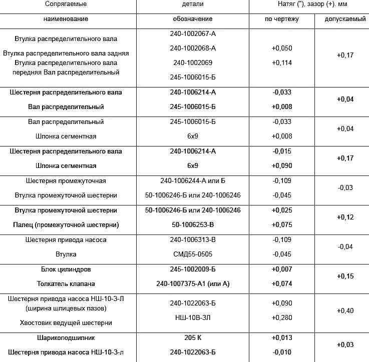
Mounting interfaces of the gas distribution mechanism