You will need: a hex wrench “6”, heads “12”, “13”, “14”, a small chisel, a hammer
We drain the oil and coolant from the engine, remove the mudguard and the auxiliary drive belt.
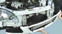
Remove the radiator, fan, coolant pump and generator.
Remove the crankshaft pulley.
The block cover can be removed without removing the head.
But at the same time, damage to the head gasket is possible, since adhesive sealant was applied to the upper end of the cylinder block cover during assembly.
In addition, the head interferes with the installation of the cover - it is difficult to achieve accurate centering of the cuff on the crankshaft sleeve, which will lead to its rapid wear.
Therefore, when disassembling the gas distribution mechanism drive, we remove the block head (see Replacing the cylinder head gasket of the ZMZ-405, ZMZ-406 engine).
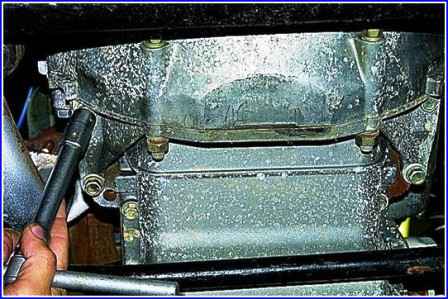
With a “14” head, we unscrew the four bolts securing the clutch crankcase amplifier to the block.
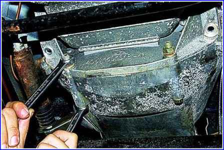
With the keys "14" and "17" we unscrew the two bolts securing the amplifier to the clutch housing and remove the amplifier.
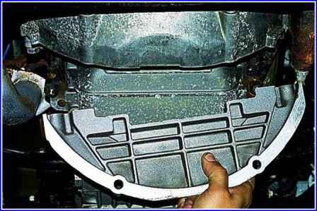
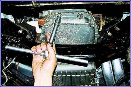
With a “13” head, we unscrew four nuts and a “12” key with eleven bolts securing the oil pan to the cylinder block.
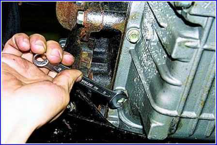
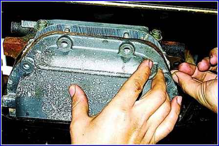
Carefully, trying not to damage the gasket, remove the pallet from the studs and put it on the beam.
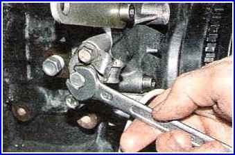
Remove the lower chain hydraulic tensioner (see ZMZ-406 engine chain hydraulic tensioner).
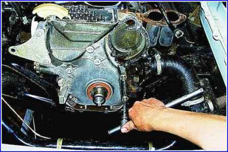
Using a 6" hex wrench, we unscrew the seven screws securing the cylinder block cover.
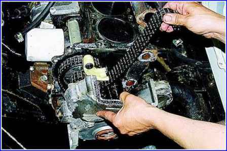
Prying off with a screwdriver, remove the cover.
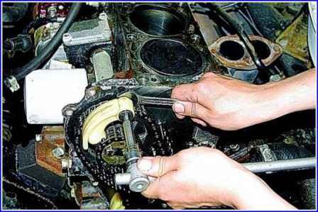
Using a 6" hex wrench, we unscrew the axle of the upper chain tensioner shoe.
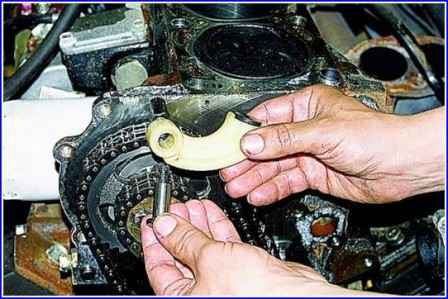
Remove the tensioner shoe.
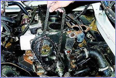
Remove the upper chain from the intermediate shaft sprocket.
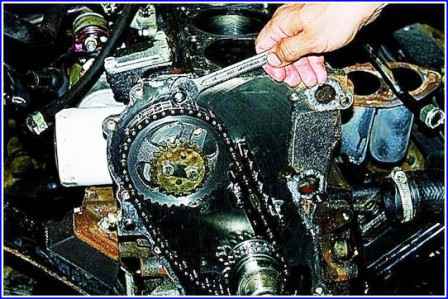
If necessary, use the “14” key to unscrew the shoe axle extension.
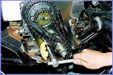
Using a “6” hex wrench, we unscrew the axle of the lower hydraulic tensioner shoe and remove the shoe.
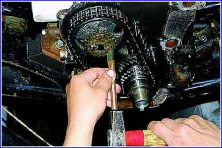
Bend the edges of the locking plate with a chisel.
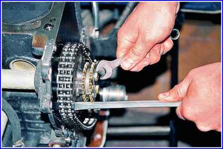
With a screwdriver, holding the intermediate shaft sprocket, unscrew the two bolts with the “12” key.
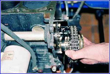
Remove the sprocket along with the lower chain from the axis of the intermediate shaft.
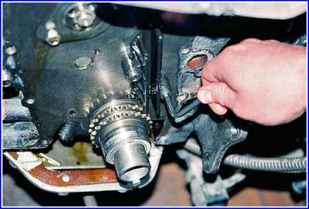
Using a 6" hex wrench, unscrew the two screws and remove the lower chain damper.
We assemble in the reverse order.
Before assembling the timing drive, we clean the mating surfaces of the cylinder block and the chain cover from the remnants of the gasket and sealant.
Install
If the crankshaft gear was removed, press it onto the crankshaft, install the O-ring and bushing.
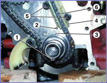
Install key 1 in the groove on the crankshaft.
Turn the crankshaft so that mark 3 on the crankshaft gear aligns with mark 2 on the cylinder block. In this case, the piston of the 1st cylinder will take the position of the top dead center
Install the chain damper 4, but do not tighten the bolts 5 for fastening the damper.
Place chain 6 on the crankshaft gear, after lubricating it with engine oil.
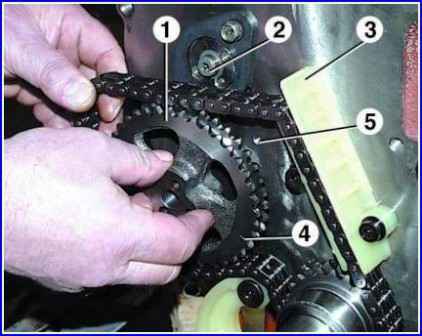
Put the chain on the driven gear 1 and install it on the intermediate shaft 2 so that the wheel locating pin enters the hole in the intermediate shaft.
In this case, mark 4 on the gear wheel must coincide with mark 5 on the cylinder block, and the chain branch passing through the damper 3 must be tensioned.
Install the countershaft drive gear so that its locating pin fits into the hole on the driven gear.
Tighten the two bolts securing the intermediate shaft gears, placing a locking plate under them.
Tighten the bolts to a torque of 22–25 Nm (2.2–2.5 kgf m) and fix them by bending the edges of the locking plate on the edges of the bolt heads.
After installing the chain, do not turn the intermediate and crankshafts.
Pressing the tensioner shoe, tension the chain and check that the marks on the gears and the cylinder block match.
Tighten the chain guide bolts.
Lubricate the upper chain with engine oil and then put it on the intermediate shaft drive gear, passing it through the hole in the block head.
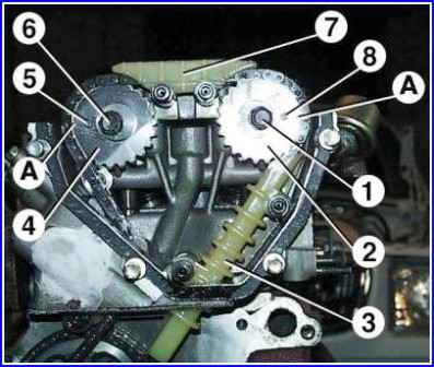
If the gear wheel 2 is mounted on the camshaft, unscrew the bolt 1 and remove the wheel 2 from the camshaft.
Put the chain on the gear wheel 2 and, slightly turning the exhaust camshaft clockwise, install the gear wheel 2 with the chain on it.
In this case, the pin 8 of the camshaft must enter the hole of the gear. Screw in bolt 1.
Turn the camshaft with the key on the square on the camshaft.
Then, turning the camshaft slightly counterclockwise, tension the chain.
The intermediate and crankshafts must not turn while doing this.
Label A must match the top plane of the block head.
Remove bolt 6 and remove gear wheel 4 from the intake camshaft.
Put a chain on wheel 4 and install wheel 4 with chain on the camshaft, while slightly turning the camshaft clockwise.
Camshaft pin 5 must fit into the gear hole.
Slightly turn the camshaft counterclockwise to tension the chain.
Mark A on gear 4 must match the upper plane of the block head.
The rest of the shafts must not rotate.
Tighten bolt 6.
Tighten bolts 1 and 6 to 46–74 Nm (4.6–7.4 kgf m), while holding the camshafts from turning with a wrench on the squares.
Install damper 3 by pushing it into the hole in the block head.
Install damper 7.
Install chain cover and water pump.
At the same time, apply a thin layer of Germesil sealant or similar to the surfaces of the cover adjacent to the cylinder block and block head.
When installing the chain cover, take care not to damage the crankshaft oil seal.
Install the hydraulic tensioners for the upper and lower chains.
Install the crankshaft pulley.
Turn on the ratchet and tighten to a torque of 104–128 Nm (10.4–12.8 kgf m), while holding the crankshaft from turning by inserting a screwdriver into the teeth of the flywheel crown and resting it on the clutch housing locating pin.
When tightening the ratchet, the flywheel pulley is pressed onto the crankshaft.
Crank the crankshaft two turns by the ratchet and set it to the TDC position. piston of the 1st cylinder. Check if labels match.
Install the front cover of the block head, applying a layer of Hermesil sealant to the surface of the cover adjacent to the block head.
Tighten the cover bolts to 12–18 Nm (1.2–1.8 kgf m).
Install all parts in reverse order.


