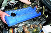
Since the hydraulic tensioners keep the chains constantly taut, regardless of chain stretch or shoe wear, there is no need to adjust the chain tension during operation
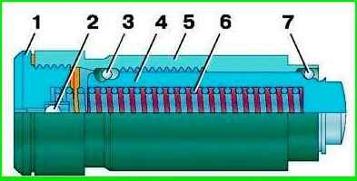
Plunger 4 is installed in body 5 .
A spring 6 is inserted into the plunger, which is compressed by a screw plug 1
Ball valve 2 is installed in plug 1
Plunger 4 is fitted with locking ring 3 and retaining ring 7.
In the figure, the tensioner is shown in a non-working "charged" state, when the retaining ring 7 keeps the plunger 4 from moving.
To bring the tensioner into working condition, to “discharge” it, you need to press the end of the plunger so that the retaining ring 7 moves into the groove of a smaller diameter on the plunger, and under the action of the spring 6 the plunger moves out of the body 5
The hydraulic tensioner is installed on the engine in a charged state.
Plunger 4, under the action of spring 6 and oil flowing through valve 2 from the engine lubrication system, presses on the tensioner shoe and keeps the chain taut.
As the chain stretches and the tensioner shoe wears out, plunger 4 moves further out of body 5, while locking ring 3 moves into the next annular groove on the body, preventing the plunger from moving in the opposite direction.
When the chain hits the tensioner shoe, for example, when the engine operation mode changes, the plunger 4 moves back into the housing 5 by the width of the groove for the locking ring 3.
At the same time, it compresses the spring 6
In addition, valve 2 closes and additional damping occurs due to the fact that oil is squeezed out through the gap between the plunger and the body.
The hydraulic tensioners of the upper and lower chains are exactly the same.
Removal and disassembly
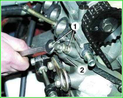
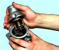
Remove the screws 1 while holding the cover 2, as the spring force acts on it.
Then, carefully remove cover 2 with the cover gasket and the noise-insulating gasket of the hydraulic tensioner
Remove the hydraulic tensioner from the channel in the block head.
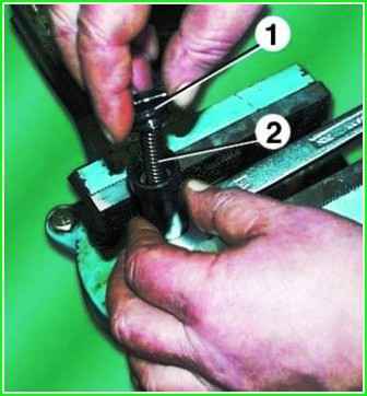
Remove screw plug 1.
The hydraulic tensioner must not be clamped in a vice, so you need to clamp the key in a vice and insert the hydraulic tensioner into it.
Remove plug 1 and take out spring 2.
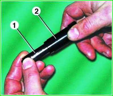
Remove plunger 1 from hydraulic tensioner body 2
Inspection
It is forbidden to dismantle the plunger and the hydraulic tensioner housing.
After disassembly, wash all parts in gasoline and dry.
Inspect the plunger, if there are scratches or nicks on its surface, the locking or retaining ring is broken, the hydraulic tensioner needs to be replaced.
Inspect the hull. If there are scuffs, deep scratches on the inner surface of the housing, or the annular grooves for the locking ring are damaged, replace the hydraulic tensioner.
The plunger in the body must move freely. If the plunger in any position “sticks” in the body, the hydraulic tensioner is replaced.
The plunger should only move in the body when the locking ring has entered the annular grooves on the body, in the direction in which it moves under the action of the spring.
If the plunger moves in the opposite direction, replace the hydraulic tensioner.
Build and install
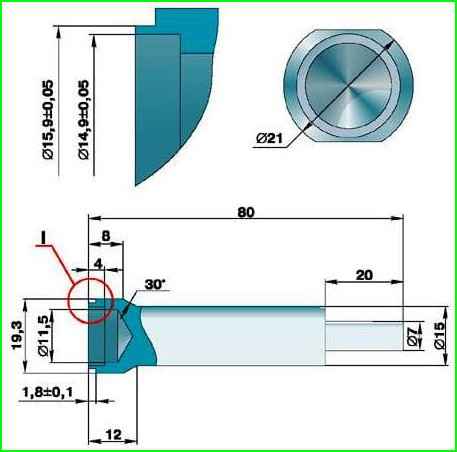
Before assembling, lubricate the plunger and the inner surface of the housing with engine oil.
To assemble the hydraulic tensioner, it is recommended to make a mandrel, the dimensions of which are shown in the figure: "Charging" the hydraulic tensioner using the ring.
Clamp the mandrel vertically in a vise.
Install the hydraulic tensioner housing on the mandrel.
Insert the plunger into the body until the plunger retaining ring stops in the mandrel.
Insert the spring into the plunger and fill the tensioner with engine oil.
Squeezing the spring inu, wrap the screw plug.
In this case, the locking ring of the plunger must enter the groove on the body and keep the plunger from moving, i.e. the tensioner will be charged.
Remove the hydraulic tensioner from the mandrel. Do not press the plunger, as this will cause the plunger retaining ring to come out of the groove on the body and the plunger will come out of the body, i.e. the hydraulic tensioner will be discharged.
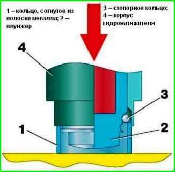
If there is no mandrel for assembling the hydraulic tensioner or it is not possible to manufacture it, you can assemble the tensioner as follows: bend the ring from a strip of metal 1.0 mm thick and about 15 mm high.
For this, you can use a piece of tape from an old band clamp; insert the plunger into the body of the hydraulic tensioner so that the retaining ring on the plunger is opposite the groove in the body; put the bent ring on the table.
Install the body with the plunger on it so that the ring fits between the body and the plunger until it stops in the retaining ring; insert a screwdriver into the plunger and with a light hammer blow on the screwdriver move the plunger down.
In this case, the retaining ring will move to a larger diameter of the groove on the plunger and enter the groove on the body, holding the plunger in a charged state; insert the spring into the plunger.
Fill the tensioner with engine oil and tighten the plug against the spring force; take out the made ring.
Do not press the plunger, so as not to discharge the hydraulic tensioner.
Lubricate the channel for the hydraulic tensioner in the head of the block with engine oil and install the hydraulic tensioner there until it stops against the tensioner shoe. Do not press the hydraulic tensioner so as not to discharge it.
Install a rubber soundproofing gasket in cover 2.
Install cover 2 with gasket on the block head, tighten bolts 1.
Unscrew plug 3 and press the hydraulic tensioner with a suitable rod through the hole under the plug, moving it to the stop, and then release it.
The hydraulic tensioner will be discharged, its body will rest against the cover 2 under the action of the spring and the chain will be tensioned. Screw plug 3 into cap 2.
In the same way, remove and install the hydraulic tensioner of the lower chain.


