")
")
")
")
")
")
Repair of the cylinder head is carried out during general engine repairs and when replacing the cylinder head gasket.
It is very important to repair the head after the motor has overheated.
During overheating, defects may occur that may not be visually visible.
Therefore, all operations to repair the cylinder head must be carefully carried out.
In many ways, the operation of the engine depends on this. And this will save you from unnecessary work and costs.
A well-repaired head is 50% of good engine performance.
Removing the cylinder head, see the article - Replacing the cylinder head gasket of the ZMZ-405, ZMZ-406 engine.
Disassembly
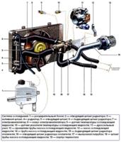
Unscrew the nuts 1 and remove the screen 5 of the phase sensor, the bracket 2 for lifting the engine and the exhaust manifold 6.

Remove the exhaust manifold gaskets. Unscrew bolt 3 and remove the 4-phase sensor.
Unscrew emergency oil pressure sensors 7 and oil pressure indicator 8.

Loosen the clamp 1 and remove the hose from the idle air control pipe.
Unscrew nuts 2 and remove reservoir 3 from the inlet pipe.
Remove the receiver gasket.

Unscrew nuts 1 and remove intake pipe 2 together with injectors and fuel line (not shown in the photo).
Remove the intake pipe gasket.

Remove the screws 1 and remove the back cover 2 of the block head.

Remove the cover gasket.

Remove hydraulic tappets for 1 valves.
It is more convenient to remove hydraulic pushers using a magnet or a suction cup.
Hydropushers cannot be interchanged, so before removing them, they must be marked so that they can be installed in their place during assembly.
Store hydraulic tappets in the same position as they are on the valves so that oil does not leak out of them.

If the design of the puller does not provide for a valve stop, place a suitable stop under it.

Compress the springs with a cracker.
To make the plate of springs come off the crackers more easily, you can apply a light blow with a hammer on the hard bipod of the cracker.

We take out two crackers with tweezers and smoothly release the springs.

Remove the top plate and two valve springs.

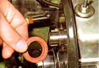
Using a puller, we remove the oil cap ...
We hook it with a screwdriver and take out the support washer 1 of the valve springs.

Turn over the cylinder head and remove the valve, marking the place of its installation, so that during subsequent assembly the valve will return to its original place.
Similarly, remove and mark the rest of the valves.

Worn valve guides are pressed out with a mandrel

Using an 8 hex wrench, we unscrew the plugs of the oil channels
Inspection, Troubleshooting and Repair
After disassembling the block head, rinse all parts in gasoline, wipe and dry.
Clean combustion chambers and valves from carbon deposits.
Inspect the block head.
If there are cracks on the bridges between the valve seats, traces of burnout and cracks on the walls of the combustion chamber, replace the block head.
Check with a metal ruler and feeler gauges if the flatness of the surface of the head adjacent to the block is broken.
To do this, put the ruler with an edge on the surface of the head of the block, in the middle, along and then across and measure the gap between the surface of the head and the ruler with a probe.
If the gap is greater than 0.1 mm, replace the head. 4.
Check the clearances in the camshaft bearings.
Check the gaps between the valve lifters and the channels for the hydraulic lifters in the block head.
The gap is calculated as the difference between the diameter of the channel and the diameter of the hydraulic pusher.
The nominal diameter of the channel for the hydraulic pusher is 35.0 +0.025 mm, the maximum allowable diameter is 35.1 mm.
The nominal diameter of the hydraulic pusher is 35.0 -0.025 and 35.0 -0.041 mm, the maximum allowable diameter is 34.95 mm.
The maximum allowable gap is 0.15 mm. If the gap exceeds the specified value, replace the hydraulic pusher.
If this still fails, replace the block head.
Inspect the valves.
If cracks are found on the working chamfer of the valve, warping of the valve head, burnout, deformation of the stem, the valve must be replaced.
Minor scratches and scratches on the valve face can be removed by lapping.
Lapping the valve to the seat is done as follows:
- - insert the valve into the block head;
- - put a valve grinding tool on the valve stem;
- - apply a thin layer of lapping paste, which is a mixture of fine abrasive powder with engine oil, to the working chamfer of the valve;
- - turn the valve in both directions with the help of the device, periodically pressing it against the seat.
An external sign of satisfactory lapping is a solid matte gray color of the working facet of the seat and valve.
After lapping, wipe the seat and valve with a clean cloth and rinse thoroughly to remove any remaining lapping paste.
To check the tightness of the valve, install it in the head of the block along with springs and crackers.
After that, put the head of the block on its side and pour kerosene into the channel closed by the valve.
If within 3 minutes. kerosene will not seep into the combustion chamber, the valve is considered sealed.
Check the condition of the valve springs. Springs that are bent or cracked or broken should be replaced.

Check the condition of the valve seats. Seat edges must be free of wear, pitting, corrosion, etc.
Minor damage (small marks, scratches, etc.) can be removed by lapping the valves.
Stronger defects can be removed by grinding.
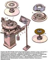
While grinding, keep the dimensions of the saddle shown in the figure
Saddle Profile engine valve mod. 4062.
After grinding, check the runout of the chamfer of the seat against the hole in the valve guide, the maximum allowable runout is 0.05 mm.
After grinding, grind the valves.
Then, thoroughly clean and blow out the head of the block with compressed air so that no abrasive particles remain in the channels closed by the valves and in the combustion chambers.
It should be noted that after grinding the seat, the valve sits deeper in the seat.
Therefore, after grinding, you need to measure the distance between the end of the valve stem pressed against the seat and the camshaft axis.
If this distance is less than 35.5 mm, replace the block head, as in this case the normal operation of the valve lifters is disrupted.
Check clearances between guide bushings and valves.
Clearance is calculated as the difference between the diameter of the hole in the sleeve and the diameter of the valve stem.
The maximum allowable gap is 0.2 mm. If the clearance is greater than specified, replace the valve and guide sleeve.
The old bushing is pressed out with a mandrel from the side of the combustion chamber.
Install new bushings with retaining rings put on them until the retaining ring stops in the plane of the block head from the side of the hole for the hydraulic pushers.
Before installation, the bushings must be cooled to -40...45°С, and the block head must be heated to a temperature of +160...175°С.
The bushing should be inserted into the head of the block freely or with little effort.
For spare parts, valve guides are supplied in three repair sizes.
First overhaul with 0.02 mm increase in bushing outer diameter.
The second one has the outer diameter of the sleeve 14.2 +0.053 and 14.2 +0.040 mm, the third one has a diameter increased by 0.02 mm from the second size.
When installing bushings of the first repair size, do not bore the hole for the bushing in the head of the block.
When installing bushings of the second and third repair sizes, it is necessary to bore the hole to a diameter of 14.2 -0.023 and 14.2 -0.050 mm.
After installing the new bushings, expand the hole for the valves in them
Then grind the valve seats as above.
In order to check the block head for cracks, you need to bring a hose for supplying compressed air to one of the holes in the cooling jacket.
Plug all holes in the head with wooden plugs.
Immerse the head in a bath of water and apply compressed air at a pressure of 1.5 atm.
In places where there are cracks, air bubbles will come out.

Having cleaned the mating plane of the head, we check the quality of the fit of the head to the block with a curved ruler.
If the deformation exceeds 0.05 mm, the flatness must be restored by machining, however, if the non-flatness exceeds 0.1 mm, the head cannot be repaired.
We wash the head with kerosene or diesel fuel, clean the oil channels from deposits.
Then we wipe the surfaces with a clean rag and blow the channels with compressed air.
Reinstall the oil channel plugs.

We press in new valve bushings through an aluminum spacer, preheating the head to 160–180°C and cooling the bushings in “dry ice” (CO 2 ).
We install the valves in the reverse order of removal, replacing the old valve stem seals with new ones
Lapping valves

Apply lapping paste to the bevel of the valve and install it in the corresponding head sleeve.

We fix the lapping tool on the valve stem and, pressing the valve against the seat, turn it in both directions by about 90 °.

Continue lapping until the sealing chamfer of the valve completely over its entire width and length becomes matte and clean
The chamfer on the valve seat should also look like this.
We wipe the rest of the paste with a rag from the valve and seat.
We assemble the cylinder head in reverse order.