")
")
")
")
")
")
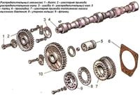
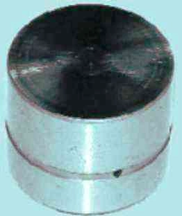
Hydraulic pushers of the engine ZMZ-406, ZMZ-405, made in the form of cylindrical pushers and located between the camshaft and valves, combine two functions:
transmitting force from the camshaft to the valves and eliminating gaps in their drive
The operation of the hydraulic pusher is based on the principle of incompressibility of engine oil, which constantly fills the internal cavity of the hydraulic pusher during engine operation and moves its plunger when a gap appears in the valve drive.
Thus, constant contact of the pusher (valve drive lever) with the camshaft cam without play is ensured.
This eliminates the need to adjust the valves during maintenance.
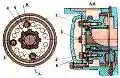
The principle of operation of the hydraulic pusher is shown in Figure 2.
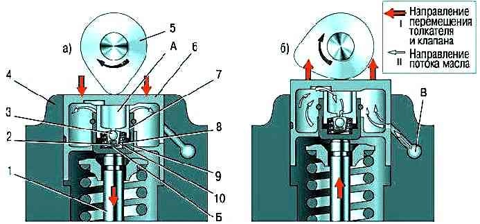
Oil under pressure necessary for the operation of the hydraulic pusher is supplied to its internal cavities "A" and "B" from the channel "C" of the engine lubrication system through the side hole in the pusher 6, made in the annular groove of its cylindrical surface.
When the valve 1 is closed, the pusher 6 (through the plunger 7) and the sleeve 9 are pressed by the expanding force of the spring 8, respectively, to the cam 5 of the camshaft and the end of the valve stem.
The pressure in the cavities "A" and "B" is the same, the check valve 3 of the hydraulic compensator is pressed against the seat in the plunger 7 by the spring 2 - there are no gaps in the valve mechanism.
When the camshaft rotates, the cam 5 runs into the pusher 6, moving it and the associated plunger 7.
Moving the plunger 7 in the sleeve 9 leads to a sharp increase in pressure in the cavity "B".
Despite small oil leaks through the gap between the plunger and the sleeve, the pusher 6 and sleeve 9 move in one piece and open valve 1.
With further rotation of the camshaft, cam 5 reduces the pressure on the pusher 6 and the oil pressure in cavity "B" becomes lower than in cavity "A".
Return valve 3 opens and passes oil from cavity "A", connected to the engine oil line, into cavity "B".
The pressure in the cavity "B" increases, the sleeve 9 and the plunger 7, moving relative to each other, select the gap in the valve mechanism.
The pressure of the oil supplied to the hydraulic pushers is regulated by a special valve installed in the cylinder head.
Since after the engine is stopped, oil drains from the channels coming from the oil pump into the oil sump, and the channels for supplying oil to the hydraulic pushers remain filled, air locks may form in the cavities of the latter after the engine is started.
To eliminate them, calibrated compensation holes are provided in the engine oil supply channels, which provide automatic purge of the cavities of the hydraulic pushers.
In addition, compensation holes allow you to slightly reduce the pressure of the oil entering the hydraulic pushers at a high engine speed, when the pressure in the hydraulic pusher cavity can become so high that its pusher, leaning on the back of the camshaft cam, slightly opens the valve at the moment , which does not correspond to the valve timing.
Almost all malfunctions of hydraulic pushers are diagnosed by the characteristic noise emitted by the gas distribution mechanism in various engine operating modes.
Noise from valves can sometimes be eliminated by slightly turning the spring or valve around the longitudinal axis.
To do this, do the following.
- 1. Rotate the crankshaft until the valve making the noise starts to open slightly.
- 2. Turn the spring a little and the valve will turn at the same time.
- 3. Start the engine. If the noise persists, repeat steps 1 and 2.
- 4. If turning the spring and valve does not give the desired result, check the condition of the spring and measure the clearances between the valve stems and guide bushings. Eliminate increased (compared to nominal) clearances.
If the valve and spring are in good condition, and the knock of the valves is still heard when the engine is running, the hydraulic pusher is faulty.
Replace it with the following.
- 1. Disconnect the wire from the negative terminal of the battery.
- 2. Remove the camshafts from the cylinder head supports

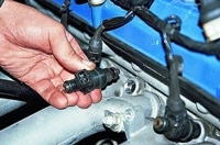
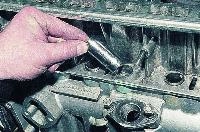
It is more convenient to remove the hydraulic pusher using a strong magnet or suction cup.
Before installing, put the new hydraulic tappet in a container with engine oil, press the tappet sleeve several times to remove air and fill it with oil.
- 3. Remove the hydraulic tappet from the cylinder head seat.
- 4. Lubricate the socket in the cylinder head with engine oil and install the hydraulic pusher in the socket.
- 5. The remaining hydraulic pushers are replaced in the same way.
- 6. Install the camshaft and timing gear parts in the reverse order of removal.
Possible malfunctions
Increased noise immediately after starting the engine:
- Oil leakage from part of the hydraulic pushers during parking
The noise that disappears a few seconds after starting the engine is not a sign of a malfunction, since oil leaked out from a part of the hydraulic pushers that were under the load of the valve springs of the open valves (the oil supply channels remained open), the lack of which is replenished at the start of the engine operation
Intermittent idling noise that disappears as engine speed increases:
- - Damaged or worn check valve ball
Replace hydraulic tappets
- - Pollution of the hydraulic pusher mechanism with wear products due to untimely oil changes or its low quality
Clean the parts of the mechanism from dirt. Use the oil recommended in the owner's manual
Increased noise during idling of a warm engine, disappearing at an increased crankshaft speed and completely absent on a cold engine:
- - Oil flow through the increased gap between the plunger and the hydraulic pusher sleeve
Replace hydraulic lifter
Increased noise that occurs at high crankshaft speed and disappears at low speed:
- - Foaming of oil when it is in excess (above the "P" mark on the dipstick) in the oil sump due to agitation by the crankshaft. The ingress of an air-foam mixture into the hydraulic pusher disrupts its operation
Bring the oil level in the oil sump to normal
- - Air intake by the oil pump when the oil level in the oil sump is too low
Bring the oil level up to normal
- - Damage to the oil receiver due to deformation of the oil sump when hitting a road obstacle
Repair or replace defective parts
Constant noise from one or more valves, independent of engine speed:
- The appearance of a gap between the pusher and the camshaft cam due to damage to the hydraulic compensator
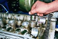
After removing the valve cover, install the camshaft cams one by one with the projections up and check for a gap between the pushers and the cams.
Sinking (for example, with a wooden wedge) the pusher of the checked hydraulic compensator, compare the speed of its movement with the speed of the others.
If there is a gap or an increased travel speed, replace the compensator.
After starting a cold engine, there may be a knock on the valve lifters, which should disappear as the engine warms up to a coolant temperature of plus 80-90 ° C.
If the knocking does not disappear more than 30 minutes after reaching the specified temperature, it is necessary to check the serviceability of the hydraulic pushers as indicated below.
A knock that appears when starting a cold engine, starting the engine multiple times (with several unsuccessful starts), starting the engine after a long stop and subsequently disappearing when the engine warms up is not a malfunction of the hydraulic pusher.
This knock of the hydraulic pushers is caused by the suction of air into the chamber of the hydraulic lifter hydraulic lifter, which leads to a loss of its rigidity and the operation of the valve drive with shocks.
The following steps are recommended to remove air:
- - start and warm up the engine to operating temperature. For 3 - 4 minutes, set the engine operation mode at a constant speed of 2500 rpm or at a variable speed range of 2000-3000 rpm, then listen to the engine idling for 15-30 seconds.
In 90% of cases, the knocking should stop,
- - if the knocking has not stopped, repeat the cycle up to 5 times;
- - in case the knock does not stop after the above work, work for another 15 minutes at a speed of 2000-3000 rpm, then listen to the engine idling for 15-30 seconds.
If the knocking has not disappeared after 5 cycles plus 15 minutes of engine operation, the following work must be done:
- - use a stethoscope (or other device that amplifies the sound) to localize the source of the knock;
- - remove the valve cover;
- - slowly turning the camshafts, set all the hydraulic pushers one by one to the “valve fully closed” position and in this position check them by applying force to the working end along the axis of movement:
- a) elastic elasticity with a short-term application of a force of about 10 N (1 kgf) indicates the presence of air in the high pressure chamber of the compensator;
- b) the appearance of a gap between the working end of the hydraulic pusher and the cam when a load of about 20-30 N (2-3 kgf) is applied for a period of 10-15 seconds and disappears after the load is removed, indicates a leak in the check valve of the compensator or wear of the hydraulic compensator plunger pair ;
- c) the presence of a gap between the working end and the camshaft cam indicates wedging of the compensator
Replace hydraulic pushers with the above signs.
In the absence of the above remarks, remove all hydraulic tappets from the cylinder head seats and check the appearance of the hydraulic tappets, camshaft cams for rough scratches, cracks, wear marks, foreign particles, contamination.
Check the oil supply to the hydraulic pushers, the running-in at the end of the hydraulic pusher and the rotation in the seat.
Replace parts with unrecoverable remarks.
Check valve spring load settlement
Replace hydraulic pushers located in places localized by a stethoscope.