")
")
")
")
")
")
The VAZ-21114 engine uses a distributed phased injection system: fuel is supplied by nozzles to each cylinder in turn in accordance with the order of operation of the engine cylinders
Electronic engine management
(ECM) consists of a controller, sensors for engine and vehicle operation parameters, as well as additional devices.
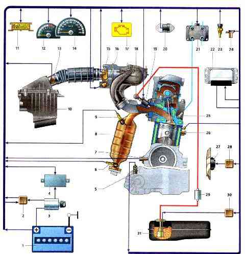
Scheme of the electronic engine control system: 1 - battery; 2 - main relay; 3 - ignition lock; 4 - immobilizer control unit; 5 - speed sensor; 6 - diagnostic oxygen sensor; 7 - sensor position of the crankshaft; 8 - collector; 9 - control oxygen sensor; 10 - air filter; 11 - diagnostic connector (diagnostic block); 12 - tachometer; 13 - mass air flow sensor; 14 - speedometer; 15 - throttle position sensor; 16 - idle speed regulator; 17 - signaling device for a malfunction of the engine control system; 18 - fuel rail; 19 - nozzle; 20 - rough road sensor; 21 - ignition coil; 22 - controller; 23 - coolant temperature sensor; 24 - phase sensor; 25 - spark plug; 26 - knock sensor; 27 - electric fan of the cooling system; 28 - electric fan of the cooling system; 29 - fuel filter; 30 - electric fuel pump relay; 31 - fuel module
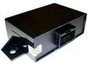
The injection system controller is the central unit of the engine management system.
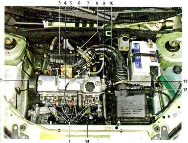
Elements of the electronic engine control system: 1 - spark plug; 2 - crankshaft position sensor; 3 - oxygen concentration sensor; 4 - knock sensor; 5 - controller and relay block of the control system; 6 - diagnostic connector and fuse box; 7 - malfunction indicator; 8 - throttle position sensor; 9 - phase sensor; 10 - coolant temperature sensor; 11 - speed sensor; 12 - mass air flow sensor; 13 - ignition coil
The controller is attached to the heater body from below, under the instrument panel.
The controller receives information from sensors and controls actuators such as fuel injectors, ignition coil, idle speed controller, oxygen concentration sensor heating element, canister purge solenoid valve, cooling system electric fan and various system relays.
When the ignition is turned on, the controller turns on the main relay, through which the supply voltage is supplied to the system elements (except for the electric fuel pump, ignition coil, electric fan, control unit and immobilizer status indicator).
When the ignition is turned off, the controller delays turning off the main relay for the time necessary to prepare for the next turn on (to complete calculations, set the idle speed controller, control the electric fan of the cooling system).
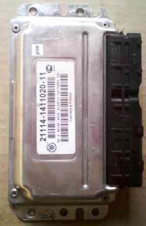
The controller is a special purpose minicomputer.
It contains three types of memory - Random Access Memory (RAM), Programmable Read Only Memory (PROM), and Electrically Reprogrammable Memory (EPROM).
RAM is used by the microprocessor to temporarily store current information about the operation of the engine (measured parameters) and calculated data.
Also, fault codes are recorded in the RAM.
This memory is volatile, i.e. when power is lost (disconnecting the battery or disconnecting the harness from the controller), its contents are erased.
The PROM stores a control program that contains a sequence of operating commands (algorithm) and calibration data (settings).
Thus, the PROM determines the most important parameters of the engine: the nature of the change in torque and power, fuel consumption, etc. The PROM is non-volatile, i.e. its contents do not change when the power is turned off.
EEPROM is used to store controller, engine and vehicle identifiers (immobilizer codes are written when learning keys) and other service codes.
In addition, the EEPROM records operational parameters (total vehicle mileage and engine operating time, total fuel consumption), as well as violations of the engine and vehicle operating modes (engine operating time: with overheating, on low-octane fuel, with exceeding the maximum allowable speed, faulty knock sensors, oxygen concentration and speed).
EPROM is a non-volatile memory and can store information when the controller is not powered.
The controller also performs diagnostic functions of the engine management system (on-board diagnostic system).
The controller determines the presence of malfunctions of the elements of the control system, turns on the malfunction indicator in the instrument cluster and stores fault codes in its memory.
If a malfunction is detected, in order to avoid negative consequences (burning of the pistons due to detonation, damage to the catalytic converter in the event of misfires in the air-fuel mixture, exceeding the limit values for exhaust gas toxicity, etc.), the controller switches the system to emergency operation modes.
Their essence is that in case of failure of any sensor or its circuit, the controller uses replacement data stored in the EEPROM to control the engine.
The engine control system malfunction indicator is located in the instrument cluster.
If the system is OK, then the warning light should come on when the ignition is turned on - thus, the ECM checks that the warning light and control circuit are working.
After starting the engine, the indicator should go out if there are no conditions for turning it on in the controller's memory.
Turning on the indicator when the engine is running informs the driver that the on-board diagnostic system has detected a malfunction, and further movement of the car occurs in emergency mode.
In this case, some parameters of the engine operation (power, throttle response, economy) may deteriorate, but driving with such malfunctions is possible, and the car can drive to the service station on its own.
The only exception is the crankshaft position sensor, if the sensor or its circuits are faulty, the engine cannot work.
After eliminating the causes of the malfunction, the indicator will be turned off by the controller after a certain delay time, during which the malfunction does not appear, and provided that there are no other fault codes in the controller’s memory that require the activation of the indicator.
Fault codes (even if the indicator goes off) remain in the controller's memory and can be read using the DST-2M diagnostic tool connected to the diagnostic connector.
When deleting fault codes from the controller memory using a diagnostic tool or by disconnecting the battery (for at least 10 s), the indicator goes out.
The sensors of the injection system provide the controller with information about the parameters of the engine and the vehicle, on the basis of which it calculates the moment, duration and order of opening of the fuel injectors, the moment and order of sparking.
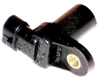
Crankshaft position sensor (DPKV)
Mounted on the oil pump housing.
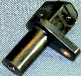
The sensor provides the controller with information about the speed and angular position of the crankshaft.
The sensor is of an inductive type, it reacts to the passage of the teeth of the drive disk, combined with the generator drive pulley, near its core.
The teeth are spaced 6˚ apart on the disc. To synchronize with the TDC of the pistons of 1 and 4 cylinders, two of the 60 teeth are cut off, forming a cavity.
When the cavity passes by the sensor, the so-called reference synchronization pulse is generated in it.
The installation gap between the core and the tops of the teeth must be within 1 ± 0.4 mm.
When the master disk rotates, the magnetic flux in the magnetic circuit of the sensor changes - alternating current voltage pulses are induced in its winding.
Based on the number and frequency of these pulses, the controller calculates the phase and duration of the pulses for controlling the injectors and the ignition coil.
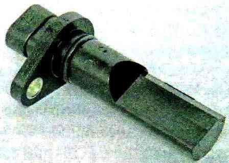
Phase sensor (DF)
Mounted on the cylinder head plug.
The principle of operation of the sensor is based on the Hall effect. A pin is pressed into the hole of the camshaft shank.
When the shaft pin passes the sensor core, the sensor outputs a low voltage pulse (about 0 V) to the controller, corresponding to the position of the piston of the 1st cylinder at the end of the compression stroke.
The controller uses the phase sensor signal for sequential fuel injection in accordance with the order of operation of the cylinders.
If the phase sensor fails, the controller switches to Non-phased fuel injection mode.
Coolant temperature sensor (DTOZH)
Mounted in the exhaust pipe on the cylinder head.
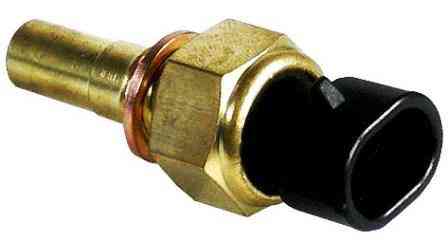
The sensor is an NTC thermistor, i.e. its resistance decreases as the temperature rises.
The controller supplies the sensor through a resistor (about 2 kOhm) with a stabilized voltage of +5 V and, based on the voltage drop across the sensor, calculates the coolant temperature, the values of which are used in most engine control functions.
If a malfunction occurs in the DTOZH circuits, the engine control system malfunction indicator lights up, the controller turns on the cooling system fan to a constant mode of operation and calculates the temperature value using a bypass algorithm.
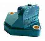
Throttle position sensor (TPS)
- mounted on the throttle axis and is a potentiometric type resistor.
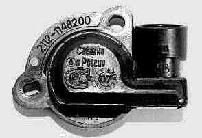
A stabilized voltage of +5 V is supplied from the controller to one end of its winding, and the other is connected to the "mass" of the controller.
A signal for the controller is taken from the third output of the potentiometer (slider).
By periodically measuring the output voltage of the TPS signal, the controller determines the current throttle position to calculate the ignition timing and duration of fuel injection pulses, as well as to control the idle speed controller.
If the TPS or its circuits fail, the controller turns on the malfunction indicator and calculates the estimated throttle position value from the crankshaft speed and mass air flow.
Mass air flow sensor (MAF)
- hot-wire type located between the air filter and the air supply hose to the throttle assembly.
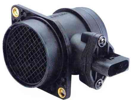
Depending on the air flow, the sensor output voltage varies from 1.0 to 5.0 V.
If the sensor fails, the controller calculates the mass air flow value from the crankshaft speed and throttle position.
DMRV has a built-in air temperature sensor (ATS), the sensitive element of which is a thermistor installed in the air stream.
The output of the sensor varies from 0 to 5.0 V, depending on the temperature of the air passing through the sensor.
If a malfunction occurs in the DTV circuit, the controller turns on the malfunction indicator and replaces the sensor reading with a fixed air temperature value (33˚С).
Knock sensor (DD)
- fixed on the front upper part of the cylinder block.
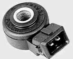
The piezoceramic sensing element of the sensor generates an AC voltage signal, the amplitude and frequency of which corresponds to the vibration parameters of the engine.
When detonation occurs, the amplitude of vibrations of a certain frequency increases. At the same time, to dampen detonation, the controller corrects the ignition timing.
Control oxygen concentration sensor (UDC)
- installed in the collector before the exhaust gas catalytic converter.
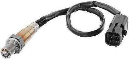
The controller calculates the duration of the fuel injection pulse from parameters such as mass air flow, engine speed, coolant temperature, throttle position.
According to the signal from the UDC about the presence of oxygen in the exhaust gases, the controller adjusts the fuel supply by the injectors so that the composition of the exhaust gases is optimal for the efficient operation of the catalytic converter.
The oxygen contained in the exhaust gases creates a potential difference at the output of the sensor ika, varying from approximately 50 to 900 mV.
A low signal level corresponds to a lean mixture (the presence of oxygen), and a high signal level corresponds to a rich mixture (no oxygen).
When the UDC is in a cold state, there is no sensor output signal, because its internal resistance in this state is very high - several MΩ (the engine control system operates in an open loop).
For normal operation, the oxygen concentration sensor must have a temperature of at least 300 ˚c, so for quick warm-up after starting the engine, a heating element controlled by the controller is built into it.
As the sensor warms up, the resistance drops and it begins to generate an output signal.
The controller constantly outputs a stabilized reference voltage of 450 mV to the sensor circuit.
Until the sensor warms up, its output voltage ranges from 300 to 600 mV. In this case, the controller controls the injection system without taking into account the voltage on the sensor.
As the sensor warms up, its internal resistance decreases and it begins to change the output voltage beyond the specified range.
Then the controller turns off the sensor heating and starts taking into account the oxygen concentration sensor signal for fuel control in closed loop mode.
The oxygen concentration sensor can be poisoned by the use of leaded gasoline or the use of sealants containing large amounts of highly volatile silicone (silicon compounds) when assembling the engine.
Silicone fumes can enter the combustion chamber through the crankcase ventilation system.
The presence of lead or silicon compounds in the exhaust gases can lead to sensor failure.
In the event of a failure of the sensor or its circuits, the controller turns on the malfunction indicator, stores the corresponding malfunction code in its memory and controls the fuel supply in an open loop.
Diagnostic oxygen concentration sensor (DDC) is used in the engine management system, made under Euro-3 toxicity standards.
DDK is installed in the catalytic converter after the exhaust gas catalytic converter.
The principle of operation of the DDC is the same as that of the UDC. the signal generated by the DDC indicates the presence of oxygen in the exhaust gases after the converter.
If the neutralizer is working properly, the readings of the DDC will differ significantly from the readings of the UDC.
The voltage of the output signal of a warmed-up FDC when operating in closed loop mode and a working neutralizer should be in the range from 590 to 750 mV.
If a malfunction of the sensor or its circuits occurs, the controller enters the malfunction code into its memory and turns on the alarm.
Vehicle speed sensor
- mounted on top of the gearbox housing.
The principle of its operation is based on the Hall effect. The sensor drive is mounted on the differential box.
The sensor outputs rectangular voltage pulses to the controller (lower level - no more than 1 V, upper level - no less than 5 V) with a frequency proportional to the speed of rotation of the drive wheels.
The number of sensor pulses is proportional to the distance traveled by the vehicle.
The controller determines the speed of the car by the frequency of the pulses. If the sensor or its circuits fail, the controller stores the fault code in its memory and turns on the alarm.
Rough Road Sensor (RGB)
- used in the engine management system, made under Euro-3 toxicity standards.
The sensor is installed in the engine compartment on the right mudguard cup.
The sensor is designed to measure the amplitude of body vibrations. The principle of its operation is based on the piezoelectric effect.
The variable load on the transmission that occurs when driving on rough roads affects the angular speed of rotation of the engine crankshaft.
At the same time, oscillations in the crankshaft speed are similar to similar oscillations that occur during misfires of the air-fuel mixture in the engine cylinders.
In this case, to prevent false detection of misfires, the controller disables this function of the on-board diagnostic system when the LND signal exceeds a certain threshold.
If the sensor or its circuits fail, the controller stores the fault code in its memory and turns on the alarm.
When the ignition is turned on, the controller exchanges information with the immobilizer (if enabled) designed to prevent unauthorized starting of the engine.
If it is determined during the communication that access to start the engine is allowed, the controller continues to function. Otherwise, the engine start is blocked.
Immobilizer control unit
- located inside the dashboard.
The ignition system consists of an ignition coil, high voltage wires and spark plugs. During operation, it does not require maintenance and adjustment, except for the replacement of candles.
Four-pin ignition coil
- is a block of two coils.
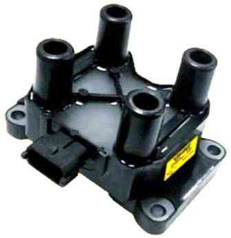
The current in the primary windings of the coils is controlled by the controller, depending on the mode of operation of the engine.
Spark plug wires are connected to the terminals of the secondary (high-voltage) windings of the coils: to one winding - the 1st and 4th cylinders, to the other - the 2nd and 3rd.
Thus, the spark simultaneously jumps in two cylinders (1-4 or 2-3) in one during the compression stroke (working spark), in the other during the exhaust stroke (idle).
The ignition coil is non-separable, it is replaced in case of failure.
A17DVRM spark plugs or equivalents
- with an interference suppression resistor with a resistance of 4-10 kOhm and a copper core.
- The gap between the electrodes of the candle is 1.0-1.1 mm.
- Wrench size 21mm
Due to the constant direction of the current in the secondary windings of the coil, the sparking current for each pair of candles operating simultaneously always flows from the central electrode to the side electrode for one candle and from the side electrode to the central one for the other.
Electroerosive wear of a pair of spark plugs will be different.
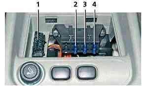
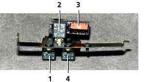
Three fuses (15 A each) and a diagnostic connector of the control system are located under the floor tunnel cover.
In addition to the fuse in the power supply circuit of the engine control system, a fuse is provided at the end of the red wire (connected to the “+” terminal of the battery), made in the form of a piece of gray wire with a cross section of 1 mm.
The control system relay box, consisting of the main relay, the electric fuel pump relay and the cooling fan relay, is located under the instrument panel console next to the controller.
When the ignition is turned on, the controller energizes the electric fuel pump relay for 2 seconds to create the necessary pressure in the fuel rail.
If during this time cranking of the crankshaft by the starter has not started, the controller turns off the relay and turns it on again after the start of cranking.
If the ignition was switched on three times in a row without cranking the crankshaft starter, then the next switching on of the electric fuel pump relay will occur only with the beginning of cranking.
When the engine is running, the composition of the mixture is regulated by the duration of the control pulse applied to the injectors (the longer the pulse, the greater the fuel supply).
When the engine is started, the controller processes the signal from the coolant temperature sensor to determine the duration of the injection pulses required for starting.
During engine start, fuel is supplied to the engine cylinders "asynchronously" - regardless of the position of the crankshaft.
As soon as the engine speed reaches a certain value (depending on on the temperature of the coolant), the controller generates a phased pulse to turn on the injectors - fuel is supplied to the cylinders "synchronously" (depending on the position of the crankshaft).
At the same time, the controller, based on the information received from the sensors, calculates the moment when each injector is turned on: fuel is injected once in one full cycle of the corresponding cylinder.
If there is no signal from the crankshaft position sensor (the shaft does not rotate or the sensor and its circuits are faulty), the controller turns off the fuel supply to the cylinders.
The fuel supply is turned off even when the ignition is off, which prevents the mixture from spontaneous ignition in the engine cylinders.
If the controller detects a misfire in one or more cylinders, the fuel supply to those cylinders is stopped and the control system malfunction indicator flashes.
During engine braking (with the gear and clutch engaged), when the throttle is fully closed and the engine speed is high, no fuel is injected into the cylinders to reduce exhaust emissions.
When the voltage drops in the car's on-board circuit, the controller increases the energy accumulation time in the ignition coil (for reliable ignition of the combustible mixture) and the duration of the injection pulse (to compensate for the increase in nozzle opening time).
When the voltage in the on-board network increases, the energy accumulation time in the ignition coil and the pulse duration decrease.
The controller controls the activation of the electric fan of the cooling system (via a relay) depending on the engine temperature, engine speed and air conditioning (if installed).
The cooling fan will turn on if the coolant temperature is too high.
In the engine management system, made to Euro-3 toxicity standards, two relays for turning on the electric fan are used.
Depending on the operating conditions of the engine and air conditioner, the controller can turn on the electric fan at high speed or at low speed - through another relay and an additional resistor
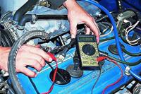
When servicing and repairing the engine management system, always turn off the ignition (in some cases it is necessary to disconnect the wire terminal from the negative battery terminal).
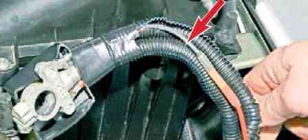
When welding on a vehicle, disconnect the engine control wiring harnesses from the controller.
Before drying the car in the oven (after painting), remove the controller.
With the engine running, do not disconnect or adjust the engine control harness connectors or the battery terminals.
Do not start the engine if the wire terminals on the battery terminals and the lugs of the ground wires on the engine are loose or dirty.