")
")
")
")
")
")
Functions of the engine management system:
- - controls the power supply of the fuel pump;
- - controls the supply of gasoline to the inlet pipeline of each cylinder in accordance with the cycles of the engine's workflow;
- - provides a spark to the candles and corrects the ignition timing, ensuring the engine does not detonate;
- - controls the air supply at the time of start.
The system consists of an electronic control unit, a set of sensors, actuators and connecting wires with connectors.
An electronic control unit is a specialized computer that receives signals from sensors and controls the executive elements of the system.
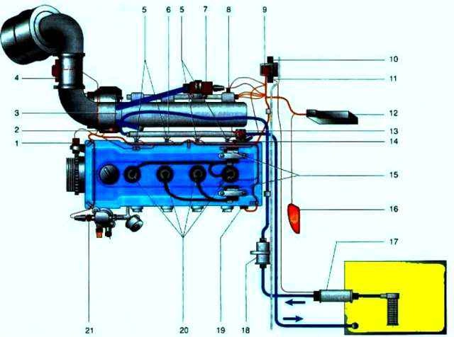
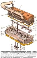
Engine control system ZMZ-405, ZMZ-406: 1 - crankshaft angular position sensor (synchronization sensor); 2 - throttle position sensor; 3 - throttle valve; 4 - mass air flow sensor; 5 - electromagnetic nozzles; 6 - fuel rail; 7 - additional air regulator; 8 - air temperature sensor in the intake manifold; 9 - diagnostic connector; 10 - relay of the engine control system; 11 - fuel pump relay; 12 - electronic engine control unit; 13 - fuel pressure regulator; 74 - knock sensor; 75 - ignition coils; 16 - indicator lamp; 17 - fuel pump; 18 - fuel filter; 79 - camshaft position sensor (phase); 20 - spark plugs; 21 - coolant temperature sensor.
Scheme of an integrated engine control system
The microprocessor of the control unit, according to the program entered into the memory of the unit, and based on the data received from the sensors, calculates the necessary signal parameters for the actuators.
The matching elements of the control unit transmit these signals to the actuators of the system.
Control system sensors: timing, camshaft position, knock, air flow, throttle position, coolant temperature and intake air.
Actuators: electromagnetic injectors, ignition coils, auxiliary air regulator, indicator lamp, electric fuel pump relay and unloader relay.
In the event of a failure of the throttle position sensor, mass air flow sensor or knock sensor, the system switches to a backup mode that allows you to get to the place of repair.
The system informs the driver about the transition to the standby mode by turning on the KMSUD indicator lamp on the instrument panel.
Operating the engine in this mode does not adversely affect its condition, however, it becomes difficult to start, throttle response worsens, fuel consumption and exhaust gas toxicity increase.
Electronic engine control unit
Information about the settings of the control system and malfunctions is stored in the memory of the unit and can be read through the diagnostic connector.
If the battery is disconnected, the fault information will be cleared. This does not affect the operation of the engine in the future, but may lead to a temporary deterioration in its performance.
The MIKAS 5.4 control unit is based on the SAB80C517A microprocessor from SIEMENS.
The software is stored in a read-only memory (ROM, ROM) with a capacity of 32 KB and random access memory (03U).
On cars with a ZMZ-4062 engine manufactured before May 1997, MIKAS 5.4 201.3763.001 control units were installed, in which the ROM chip 201.001 was installed.
Since August 1998, cars have been equipped with MIKAS 5.4 201.3763.003 units, in which the ROM 201.003 chip is installed, which controls the electric fan and the air conditioning compressor.
The control unit diagnoses the circuits of sensors and actuators, and also checks the health of its own circuit.
When a malfunction is detected, the unit turns on the signaling lamp KMSUL.
The control unit diagnostic system has several modes of operation.
Working mode
When the ignition is on, the electronic control unit constantly monitors most of the incoming and outgoing signals.
About malfunctions that appear and disappear, the unit informs with a short (about 0.5 s) turning on of the indicator lamp.
At the same time, fault codes that appear more than once every two minutes are stored in the memory of the electronic unit.
DTCs that do not appear within two hours will be erased from memory.
A permanently lit indicator lamp informs about a malfunction that is constantly present in the system.
Dir displaying diagnostic information
In this mode, the electronic unit, using the indicator lamp, displays the fault codes recorded and stored in memory.
Each fault has a two- or three-digit flash code.
Each digit of the code corresponds to a series of short (0.5 s) flashes of the lamp. There is a pause between the series (about 1.5 s).
After all the digits of one code have been transmitted (2 or 3 series of flashes, depending on whether the code is two or three digits) there is a long (about 4 s) pause.
For example: fault code "131" will be transmitted in the following sequence: one short flash, short pause, three short flashes, short pause, one short flash, long pause.
The code for each fault is repeated three times.
Working mode with diagnostic equipment
For a more complete check of the engine management system, a special tester 08T-2 is connected to the diagnostic connector.
Only specialists with the necessary equipment can carry out such work.
Error code deletion mode
Error codes are erased from memory when the battery is disconnected.