")
")
")
")
")
")
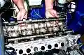
ZMZ-402 engines are installed on Volga, UAZ, Gazelle cars
The engines have proven themselves well during operation
Unpretentious and easily repairable, in garage conditions.
Inline four-cylinder engines equipped with carburetors and contactless ignition system.
Both are similar in design, but the engine mod. 4021 deformed.
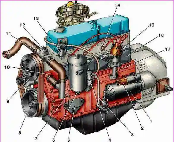
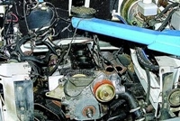
Fig. 1. Type of engines mod. 402 and 4021 on the left side
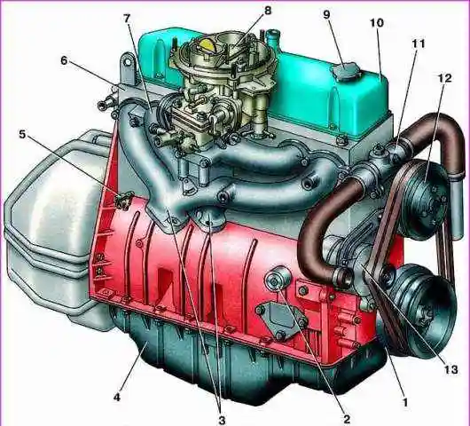
Fig. 2. Type of engines mod. 402 and 4021 on the right side
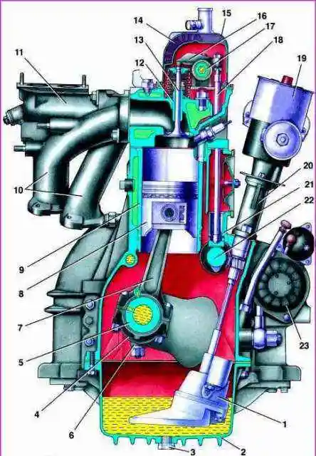
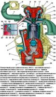
Fig. 3. Cross section of engines mod. 402 and 4021
The cylinder block is cast from an aluminum alloy. Cylinder liners cast from wear-resistant cast iron are inserted into it.
Five main bearing supports are made in the lower part of the block.
The main bearing caps are made of ductile iron and are attached to the block with two studs.
The bearing caps are processed together with the block, so they cannot be interchanged.
The cover of the first bearing is machined at the ends together with a block for installing two thrust washers to limit the axial movement of the crankshaft.
On the covers of the 2nd, 3rd and 4th bearings, their serial numbers are stamped.
At the front end of the block, a timing gear cover is attached, cast from an aluminum alloy, into which the crankshaft collar is inserted.
The clutch housing is attached to the rear end of the block.
The oil sump is attached to the block from below, the cylinder head is attached to the top.
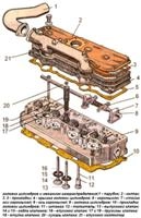
The head of the block is cast from an aluminum alloy. It has vertically mounted intake and exhaust valves.
The valves are driven by a camshaft located in the cylinder block through pushers, rods and rocker arms.
The axis of the rocker arms is installed in the head of the block on the racks. Seats and valve guides are installed in the block head with a large interference fit.
Combustion chambers are made in the lower part of the block head.
Engine block heads mod. 402 and 4021 differ in combustion chamber volume and height.
Height of engine block head mod. 402 is equal to 94.4 mm, mod. 4021 - 98 mm.
At the top, the head of the block is closed with a cover stamped from sheet steel.
The pistons are cast from aluminum alloy, the piston bottom is flat.
For the correct installation of the piston in the cylinder, the inscription "Front" is cast on the side wall near the boss under the piston pin.
The piston is installed in the cylinder so that this inscription is facing the front of the engine.
Each piston has two compression rings and one oil scraper ring. The top compression ring is cast from ductile iron.
The working surface of this ring is coated with a layer of chromium to increase wear resistance. The working surface of the lower compression ring,
cast from gray cast iron, coated with a layer of olova, which improves its running-in.
There is a groove on the inner surface of this ring. The ring should be installed with this groove up to the piston bottom.
The oil scraper ring consists of four elements: two steel discs and two expanders, axial and radial.
The working surface of the disks is covered with a layer of chromium. The piston is attached to the connecting rod with a "floating" type piston pin, i.e. the pin is not fixed either in the piston or in the connecting rod.
The finger is kept from moving by two spring retaining rings, which are installed in the grooves of the piston bosses.
Forged steel connecting rods, with an I-section rod. A tin bronze bushing is pressed into the upper end of the connecting rod.
The bottom end of the connecting rod with a cover that is attached with two bolts. The nuts of the connecting rod bolts are locked with Unigerm-9 sealant.
The connecting rod caps are machined together with the connecting rod, so they cannot be moved from one connecting rod to another.
Cylinder numbers are stamped on the connecting rods and connecting rod caps.
In the rod of the connecting rod at the lower head there is a hole for lubricating the cylinder mirror.
This hole should point to the right, away from the camshaft.
The mass of the pistons assembled with the connecting rod must not differ by more than 12 g for different cylinders. Thin-walled connecting rod bearings are installed in the lower head of the connecting rod.
The crankshaft is cast from ductile iron. The shaft is kept from axial movement by thrust washers mounted on the front neck.
At the rear end of the shaft there is a socket for installing the ball bearing of the gearbox input shaft. A gray cast iron flywheel is attached to the rear end of the crankshaft with four bolts.
Possible malfunctions of the ZMZ-402 and ZMZ-4021 engines
Cause of failure (Remedy)
Engine won't start
Lean mixture (popping in carb):
- the mesh filter of the carburetor, fuel pump or fine fuel filter is clogged
Wash the filter in unleaded petrol and blow it out with compressed air
- the diaphragm is torn or the tightness of the fuel pump valves is broken
Replace diaphragm or valves
- water in the sump or fuel line has frozen
Heat the sump or fuel line with hot water
- clogged fuel line
Blow out the fuel line
- the carburetor air damper does not close completely;
Adjust the air damper actuator
- clogged jet: main fuel and idle;
Rinse in unleaded petrol and blow jets with compressed air
- the fastening of the carburetor to the intake pipe or the intake pipe to the cylinder head has loosened;
Tighten fasteners, replace gaskets if necessary
- low fuel level in the carburetor float chamber
Adjust the fuel level, see the article Adjusting the K-151 carburetor
- the EGR valve sticks in the open position
Replace recirculation valve
Rich combustible mixture (pops in the muffler when starting the engine):
– carburetor choke does not fully open;
Adjust the air damper actuator
- the tightness of the fuel supply valve is broken;
Replace the valve seal
- the tightness of the float is broken;
Repair the float or replace the float
- air jets of dosing systems are clogged;
Rinse jets with unleaded petrol and blow with compressed air
- the adjustment of the mixture quality screw is violated;
Adjust the desired composition of the mixture
- too high fuel level in the carburetor float chamber
Adjust fuel level
The engine does not start in cold weather:
- The air damper does not close
Adjust the air damper actuator
Engine runs erratically at idle
- High or low fuel level in the carburetor float chamber
Adjust fuel level
- Wrong idle speed
Adjust the desired composition of the mixture
- A large amount of water in the sump of the fine fuel filter and the fuel tank
Drain sediment from filter and tank
- Incorrect adjustment of clearances in the valve drive
Adjust valve clearances
- The fastening of the carburetor, intake pipe, gas pipeline has loosened
Tighten fasteners, replace gaskets if necessary
Increased toxicity of exhaust gases
- Rich I'm a combustible mixture
See "Engine won't start (Rich mixture)"
- Adjustment of gaps in the valve drive is broken
Adjust valve clearances
The engine does not develop full power and does not have sufficient throttle response:
- Faulty carburetor accelerator pump
Check pump flow, replace damaged parts
- Low fuel level in the carburetor float chamber
Adjust fuel level
- Adjustment of gaps in the valve drive is broken
Adjust valve clearances
- Carburetor throttles do not open fully
Adjust the throttle actuator
- Poor combustible mixture
See "Engine won't start (lean mixture)"
- Clogged air filter element
Replace filter element
- Adjustment of gaps in the valve drive is broken
Adjust valve clearances: article - Adjusting valve clearances ZMZ-402
- The position of the dampers "Winter-Summer" does not correspond to the season
Set dampers for the season
Increased fuel consumption
- Poor or rich combustible mixture
See "Engine won't start"
- Clogged air filter element
Replace filter element
- Wrong initial ignition timing
Adjust the initial ignition timing: article - Adjusting the ignition timing ZMZ-402
- The vacuum corrector of the ignition distributor is faulty
Replace vacuum corrector or distributor
- The tightness of the power supply system is broken
Restore tightness
- Increased resistance to vehicle movement
Check and adjust the brake system, wheel bearings, tire pressure
Engine overheating
- Faulty thermostat
Replace thermostat
- Weak tension of the fan and water pump drive belts
Adjust belt tension
- Wrong initial ignition timing
Adjust ignition timing
- Poor combustible mixture
See "Engine won't start (lean mixture)"
- Severe contamination of the radiator
Rinse the cooling system, flush the radiator with a jet of water
- Increased resistance to vehicle movement
Check and adjust the brake system, wheel bearings, tire pressure
- Faulty water pump
Replace pump
- The engine continues to run after the ignition is turned off
Motor Overheat See "Motor Overheat"
- Low octane fuel used
Use fuel with the correct octane rating
Knock knocks in the engine
- Early ignition timing
Adjust ignition timing
- A large layer of soot on the walls of the combustion chambers and piston bottoms
Clean carbon deposits
- Low octane fuel used
Use fuel with the correct octane rating
Insufficient oil pressure on a warm engine
- Faulty or clogged oil pressure reducing valve
Wash the valve parts and the seat in the oil pump housing, if necessary, replace the spring or valve
- Faulty oil pressure sensor or gauge
Check the pressure with a reference pressure gauge, replace the defective device
- Engine overheating
Turn on the oil cooler, eliminate the cause of overheating
- Large wear of the main bearing shells
Replace Earbuds
- Wear of oil pump parts
Replace the gasket between body and cover with a thin paper gasket or replace the pump
Increased oil consumption
- Large wear of piston rings
Replace piston rings
- Clogged crankcase ventilation system
Rinse with unleaded petrol and blow out with compressed air the ventilation hoses and ducts in the intake pipe and the parts of the oil separator in the rocker cover
- Oil leakage through engine seals
Tighten connections, if necessary, replace gaskets or seals
- Large wear or destruction of valve stem seals
Replace caps
Engine knocks
- Wear of the connecting rod and piston group oops
Repair the engine
- Large gaps between rocker arms and valves
Adjust valve clearances
- Large gaps between valve stems and guide bushings
Replace worn parts or valve head assembly
- Wear of camshaft cams and pushers
Replace worn parts
- Large gap between thrust rings and crankshaft
Replace Thrust Rings