Checking the details of the cylinder head of the 1AZ-FE engine
We check the parts to determine the possibility of further operation of the cylinder head parts
Checking the cylinder head
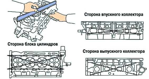
Using a ruler and a flat feeler gauge, check the warping of the cylinder head surfaces mating with the cylinder block surface and with the surfaces of the intake and exhaust manifolds (Fig. 1).
Maximum Warp Tolerance:
- cylinder block side - 0.05 mm;
- Intake manifold side - 0.08mm;
- Exhaust manifold side - 0.08mm
If the warp plane is greater than the maximum, replace the cylinder head.
Use the dye to check for cracks in the combustion chambers, inlet and outlet ports, and at the gas interface.
If there are cracks, replace the cylinder head.
Checking the cylinder head valve seats
Apply a thin coat of white to the bevel of the valve.
Lightly press the valve face against the seat, but do not rotate the valve.
Then remove the valve and inspect the valve seat and bevel.
If the paint remains around the entire circumference (360°) of the valve chamfer, then the valve is concentric.
If not, replace the valve.
If the paint appears around the entire circumference (360°) of the valve seat, the valve guide (sleeve) and valve seat are concentric.
Otherwise, regrind the bevel.
Make sure the contact patch is in the middle of the valve face and is 1.0-1.4mm wide (Figure 2).
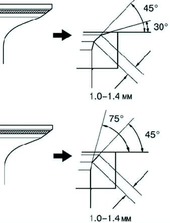
If the contact patch is too high, correct the bevel with 30° and 45° taper cutters.
If the contact patch is too low, correct the bevel with 75° and 45° taper cutters (fig. 3).
Checking the camshaft end play
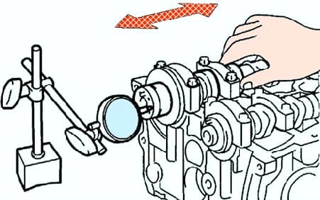
Install the camshafts.
Measure the axial play with an indicator by moving the camshaft back and forth (Fig. 4).
Nominal backlash:
- inlet - 0.040-0.095 mm;
- outlet - 0.080–0.135 mm.
Limit clearance:
- inlet. – 0.11 mm;
- outlet - 0.15 mm.
If the end play is greater than the maximum, replace the camshaft.
If necessary, replace bearing caps and cylinder head.
Checking the radial play in the camshaft bearings
Clean the running surfaces of the bearing caps and camshaft journals.
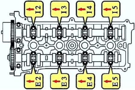
Install the front bearing shell.
Lay the camshaft in the bed of the cylinder head.
Place a piece of plastic gauge on each camshaft journal.
Install the bearing caps.
Tighten the bolts of the covers with the tightening torque:
- #1 - 30 Nm (301 kg cm);
- #2 - 30 Nm (301 kg cm);
- #3 - 9 Nm (92 kg cm).
Valve spring check
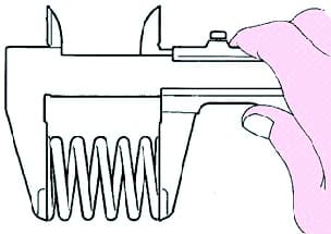
Measure the free length of the spring with a caliper (Fig. 6).
Valve spring length: 45.70 mm.
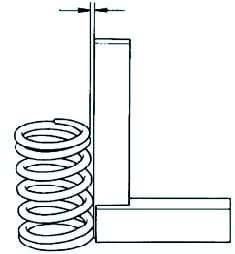
Using a metal square (90°), check the valve spring non-perpendicular clearance (fig. 7).
Out-of-perpendicular clearance limit: 1.6 mm.
Checking the cylinder head valve length
Check the overall valve length.
Nominal length:
- inlet valve - 101.71 mm;
- exhaust valve - 101.15 mm.
Limit length:
- inlet valve - 101.21 mm;
- outlet valve - 100.70 mm.
If the overall length is less than the minimum, replace the valve.
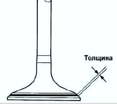
Checking the thickness of the cylinder head valve disc
Check the thickness of the valve head with a vernier caliper.
Standard intake valve thickness: 1.05 - 1.45 mm.
Minimum tolerance: 0.5 mm.
Standard thickness of exhaust valves: 1.20 - 1.60 mm.
Minimum tolerance: 0.5 mm.
If the thickness of the cylindrical part of the poppet is less than the minimum allowable value, replace the valve.
Measuring cylinder head valve stem diameter
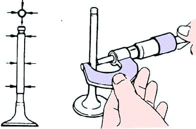
Measure the valve stem diameter with a micrometer (fig. 8).
Valve stem diameter:
- inlet valve - 5.470-5.485 mm;
- exhaust valve - 5.465-5.480 mm.
Checking the inner diameters of the cylinder head valve guides
Check the inner diameters of the valve guides.
Using an inside gauge, measure the inside diameters of the valve guides at three levels.
The inner diameter of the sleeve is 5.510–5.530 mm.
Make a calculation by subtracting the valve stem diameter and the guide bushing inner diameter, and thus establish the standard backlash between the valve stem and its guide.
Standard backlash value:
- inlet - 0.025-0.060 mm;
- outlet - 0.030–0.065 mm.
Max tolerance:
- inlet - 0.08 mm;
- outlet - 0.10 mm.
If the clearance is greater than the maximum, replace the valve and guide sleeve.
Checking tappets and tappet bores in the cylinder head housing
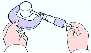
Measure the diameter of the pusher with a micrometer (Fig. 9).
Pusher diameter - 30.966–30.976 mm.
Make a calculation by subtracting the tappet diameter from the tappet bore diameter in the head housing and determine the clearance.
- Standard clearance is 0.033-0.059mm.
- The limit clearance is 0.079 mm.
If the gap exceeds the maximum allowable, replace the pusher.
Replace the cylinder head if necessary.
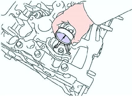
Check the tappets and tappet bores in the cylinder head housing.
Using an inside gauge, measure the diameters of the tappet bores in the cylinder head (Fig. 10).
Bore diameter - 31.000–31.025 mm.
The warping limit is 0.7 mm.
Check for buckling on the exhaust manifold contact surface.
If warpage exceeds the maximum, replace the manifold.


