Engine control sensors 1az-fe
The sensors of the engine management system transmit information to the electronic control unit, from which the ECU calculates the parameters for fuel injection control and ignition timing control
Air flow sensor
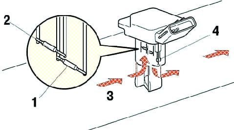
The plug-in type air flow sensor allows a portion of the intake air to flow through the area of the sensing element.
Directly measures intake air mass and flow rate, measurement accuracy is improved and airflow resistance is reduced.
The air flow sensor has a built-in intake air temperature sensor.
Crank angle sensor
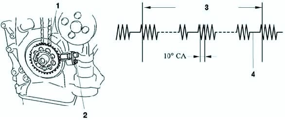
The crankshaft timing rotor has 34 teeth, 2 teeth are missing.
The crank angle sensor (see fig. 2) outputs crankshaft rotation signals every 10°, the missing teeth are used to determine top dead center.
Camshaft position sensor
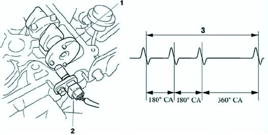
The camshaft position sensor (fig. 3) is mounted on the left side of the cylinder head.
To determine the position of the camshaft, there is a protrusion on the timing rotor, when it passes next to the sensor, 1 pulse is generated for every 2 revolutions of the crankshaft.
Throttle position sensor
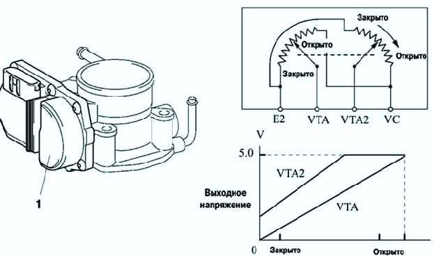
This sensor converts the throttle opening angle into electrical signals with two different characteristics and transmits them to the engine's electronic control unit (Fig. 4).
One signal (VTA) for voltage ramp over the full throttle angle range, the other signal (VTA2) for bias voltage.
Fuel pedal position sensor
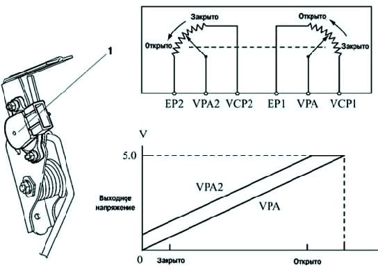
This sensor converts the angle of rotation of the fuel control pedal into electrical signals with two different characteristics and transmits them to the engine electronic control unit (Fig. 5).
One signal (VPA) for voltage ramp over the entire pedal angle range, the other signal (VPA2) for bias voltage.
EFI system electronic fuel injection system
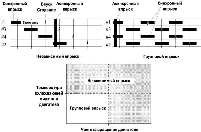
Electronic Fuel Injection Type L Air intake with hot-wire type air flow sensor.
An independent injection system is used (in which fuel is injected into each cylinder once every two revolutions of the crankshaft).
In addition, group injection is used when starting the engine (fuel is injected once into two cylinders for each revolution of the crankshaft).
There are two operating modes of the fuel injection system:
- a) synchronous injection, at which the basic injection duration is corrected according to the signals of the sensors so that fuel injection always occurs at a certain position of the crankshaft;
- b) asynchronous injection, in which fuel is injected when requests are detected from sensor signals, regardless of the angle of rotation of the crankshaft.
In addition, to protect the engine and increase fuel efficiency, the system performs a fuel cut-off, at which fuel injection is temporarily stopped according to driving conditions.
ETCS-I (Electric Throttle Control System)
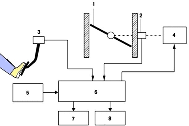
In a conventional throttle valve, throttle opening is uniquely determined by the force on the throttle pedal.
In contrast, with ETCS-i, the ECM calculates the optimum throttle opening angle that suits driving conditions and uses the throttle motor to control the opening.
The throttle cable and lever have been removed, and the position sensor has been installed on the throttle pedal.
The ECM controls the throttle motor by setting the target throttle angle according to the vehicle's driving condition.
It controls the throttle to keep the engine idling at a constant speed
Shock protection
During gear changes, throttle control is synchronized with the operation of the ECT (Electronic Transmission) system to reduce shock loads
Automatic speed control system
An electronic engine control unit with an integrated cruise control electronic control unit directly actuates the throttle valve for cruise control
VVT-I (Intelligent Valve Timing)
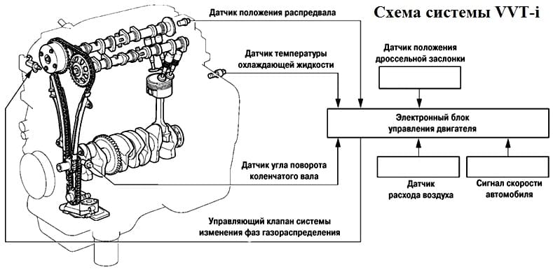
The VVT-i system is designed to control the intake camshaft over a wide range of 50° (crank angles)
It provides a valve opening or closing point that is optimally matched to the engine's operating conditions, thus increasing torque in all speed and fuel efficiency ranges and reducing exhaust emissions.
The actual intake valve opening or closing timing is determined by the camshaft position sensor to constantly compare with the target valve opening or closing timing and generate the appropriate control action.
Engine cooling fan control
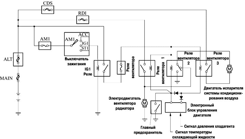
Unlike the previous electric fan system, the coolant temperature switch has been removed.
Instead, a coolant temperature sensor is used to control the fan motor, simplifying the system.
The cooling fan control system turns on/off the 3 fan relays according to the coolant temperature and the operating mode of the air conditioning system.
When the fans are on, the two fan motors can run at low (series) or high (parallel) speed.


