Checking the front seat adjustment switch
Check for continuity between the front seat adjustment switch connector pins
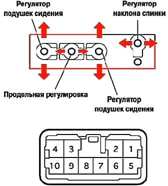
If the results are not as shown in the table, replace the switch.
Longitudinal adjustment
|
Output number |
Position switch |
Result |
|---|---|---|
|
1-94-6 |
Forward |
conducted |
|
6-4-9 |
Disabled |
conducted |
|
4-91-6 |
Back |
conducted |
Cushion adjustment (driver's seat)
If the results are not as shown in the table, replace the switch.
|
Output number |
Position switch |
Result |
|---|---|---|
|
1-10 4-5 |
Up |
conducted |
|
5-4-10 |
Disabled |
conducted |
|
1-5 4-10 |
Down |
conducted |
Cushion adjustment (passenger seat)
|
Output number |
Position switch |
Result |
|---|---|---|
|
1-7 4-8 |
Up |
conducted |
|
7-4-8 |
Disabled |
conducted |
|
1-84-7 |
Down |
conducted |
Seat back adjustment
|
Output number |
Position switch |
Result |
|---|---|---|
|
1-32-4 |
Forward |
conducted |
|
2-4-3 |
Disabled |
conducted |
|
1-2 3-4 |
Back |
conducted |
Checking the seat adjustment motors
Connect the battery to the terminals of the motor connector, check by changing the polarity of the voltage that the armature rotates in two directions.
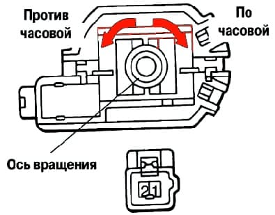
If the armature does not rotate in at least one direction, replace the motor.
Standard check
|
Polarity |
Action |
|---|---|
|
Battery (+) ─ 1 Battery (─) ─ 2 |
Counterclockwise |
|
Battery (+) ─ 1 Battery (─) ─ 2 |
Clockwise |
Checking thermal fuses
Connect the positive battery terminal to terminal "1", the positive ammeter wire to terminal "2", the negative ammeter wire to the negative battery terminal.
Turn on the motor to be tested, after stopping the seat in an extreme continue to apply voltage in this position.
Make sure the current drops to less than 1A in 4 to 90 seconds (fuse blows).
Disconnect the wires.
Approximately one minute later, apply reverse polarity voltage to the motor leads, the motor should turn on.


