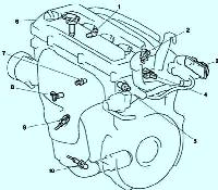
The valves are opened and closed directly by the four camshafts (see fig. 1)
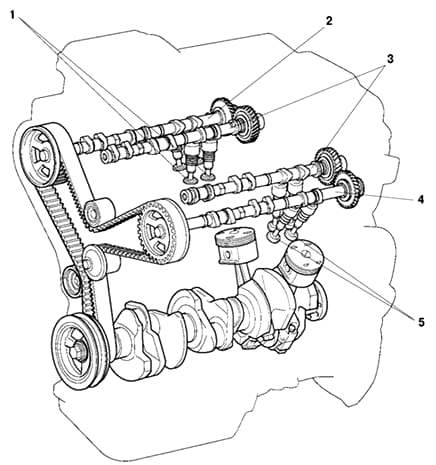
The exhaust camshafts are driven by a toothed belt, while the intake camshafts are driven by gears on the exhaust camshafts.
Camshafts
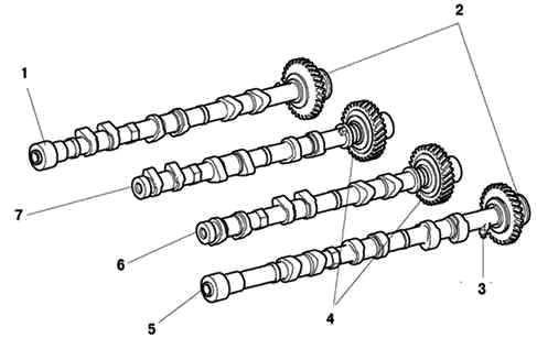
Camshafts (fig. 2) are made of cast iron alloy.
Due to the use of DIS (Direct Ignition System), a timing rotor is installed on the No. 4 camshaft to operate the camshaft position sensor.
The intake camshafts are driven by gears on the exhaust camshafts.
The gear train used to drive the exhaust camshaft provides mesh clearance adjustment and gear drive noise suppression.
Intake and exhaust valves and valve lifters
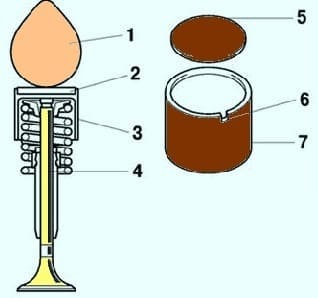
Reduced valve stems are used to reduce inlet and outlet flow resistance (see Figure 3) and to reduce valve weight.
The shim is located directly on the valve lifter.
This design allows you to change the shim without removing the camshaft, which improves serviceability when adjusting valve clearance.
To improve serviceability when replacing shims, there is a cutout in the valve lifter.
There are 17 shim sizes available, in increments of 0.050 mm, ranging from 2.5 to 3.3 mm.
Timing timing belt
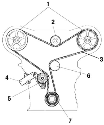
The timing belt tooth configuration has been developed to reduce noise and enable power transmission at high load factors.
Timing belt tensioner
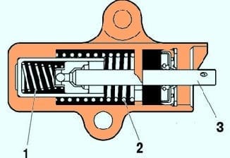
The timing belt tensioner uses a spring and an oil damper to keep the timing belt under tension at all times.
Also, the timing belt tensioner performs the function of suppressing the noise produced by the timing belt.


