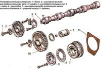
To compensate for the thermal expansion of the valve, the gap between the end of the valve stem and the camshaft cam is structurally set
With an increased clearance, the valve will not open fully, with a reduced clearance, it will close completely.
- - If the clearance in the valves is increased, then a characteristic ringing knock will appear in the upper part of the engine. Vibration will appear.
- - If the valve clearance is small, the engine will run very "hard".
There is such a term ("hard" engine and "soft" engine). The engine runs “hard”, as if the crankshaft has been pulled over.
The engine is running tight. The engine is rapidly overheating. And as a result, severe wear of the gas distribution mechanism.
Gap is measured on a cold engine (at +20°c) between the camshaft cam (the cam must point upwards from the tappet) and the valve tappet shim.
The nominal clearance for the intake valve is (0.2±0.05) mm, for the exhaust valve it is (0.35±0.05) mm.
The gaps are adjusted by selecting the thickness of the shims. As spare parts, washers with a thickness of 3 to 4.5 mm are available in 0.05 mm increments.
Counting from the camshaft drive:
- - the first, fourth, fifth and eighth valves - exhaust;
- - the second, third, sixth and seventh valves are inlet.
It is recommended to remove the spark plugs to make it easier to turn the crankshaft.
The retainer must be installed between the camshaft and the edge of the tappet.
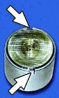
In order to remove the adjusting washer more easily, two grooves are machined in the pusher. Turn the pusher so that it is more convenient to pick up the puck.
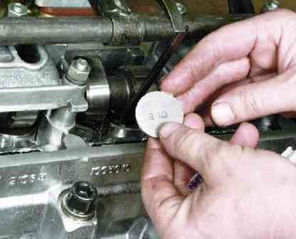
The thickness of the new washer is calculated using the formula:
H=B+A-C, where:
- - A - measured clearance, mm;
- - B — old washer thickness, mm;
- - C — nominal clearance, mm;
- - Н — new washer thickness, mm.
Example (for inlet valve):
- A = 0.26 mm,
- H = 3.75 mm,
- C= 0.2 mm,
then H = 3.75 + 0.26 - 0.2 = 3.81 (mm).
Within the clearance tolerance of ±0.05 mm, we select the washer closest in thickness (3.8 mm).
Turn the crankshaft clockwise with a wrench on the crankshaft pulley bolt or alternator pulley bolt.
It is forbidden to turn the crankshaft using the camshaft pulley bolt.
Completing task:
Remove the engine screen.
Disconnect the throttle cable from the throttle assembly sector.
Having unscrewed the three fastening nuts, remove the throttle cable bracket and move the bracket with the cable to the side.
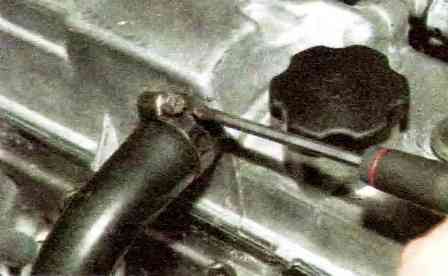
Use a Phillips screwdriver to loosen the clamp of the lower crankcase ventilation hose and remove the hose from the pipe of the cylinder head cover.
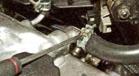
Using a Phillips screwdriver, we loosen the clamp of the crankcase ventilation hose (main circuit), and remove the hose from the pipe of the cylinder head cover.
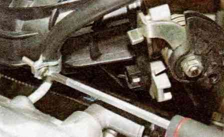
Using a Phillips screwdriver, loosen the clamp of the crankcase ventilation hose (idling circuit) and disconnect the hose from the pipe of the cylinder head cover.
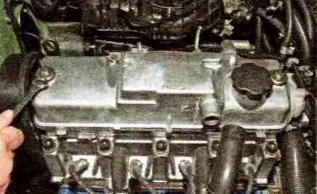
Using a 10 key, unscrew the two nuts securing the cylinder head cover and remove the washers
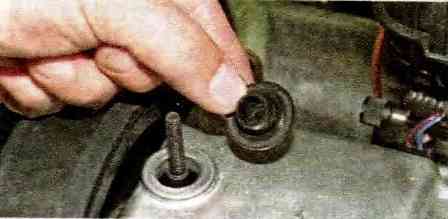
Remove the two rubber bushings
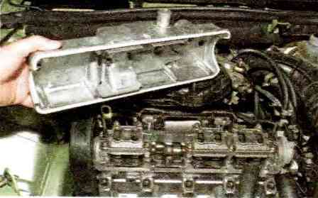
Remove the cylinder head cover
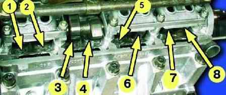
Counting from the camshaft drive, the first, fourth, fifth and eighth valves are exhaust; the second, third, sixth and seventh are intake.
Remove the front cover of the timing belt (see "Checking the condition and replacing the timing belt")
The procedure for checking and adjusting clearances in the valve drive mechanism is as follows.
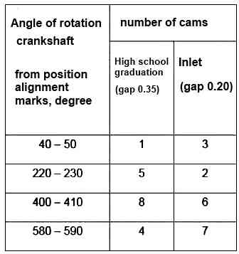
We turn the crankshaft by the bolt of the generator drive pulley clockwise until the alignment marks on the camshaft pulley and the rear cover of the timing belt are aligned.
Then we turn the crankshaft clockwise another 40 - 50 ° (2.5-3 teeth on the camshaft pulley).
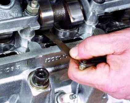
In this position of the shafts, we check the gaps at the first and third camshaft cams with a set of probes.
The gap between the camshaft lobes and shims should be 0.20 mm for intake valves and 0.35 mm for exhaust.
The clearance tolerance for all jaws is 005 mm.
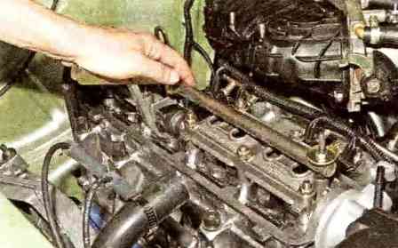
If the clearance differs from the norm, then we install a device for adjusting the valves on the studs of the camshaft bearing housings.
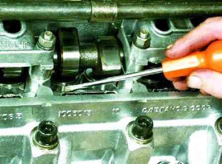
We turn the pusher so that the slot in its upper part faces forward (along the direction of the car).
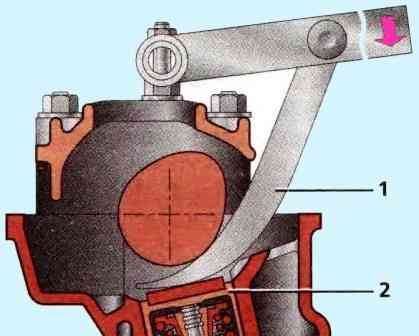
We introduce the “fang” of the device between the cam and the pusher.
We press down on the lever of the device, we sink the pusher with the “fang”.
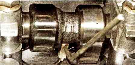
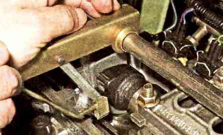
We install a retainer between the edge of the pusher and the camshaft, which holds the pusher in the lower position
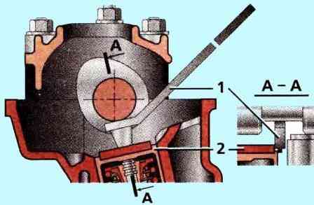
Move the fixture lever to the top position
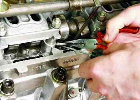
Use tweezers through the slot and remove the adjusting washer
In the absence of a device for adjusting the Apanov, you can use two screwdrivers.
With a powerful screwdriver, leaning on the cam, we press the pusher down.
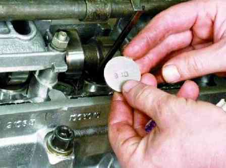
Inserting the edge of another screwdriver (with a blade width of at least 10 mm) between the edge of the pusher and the camshaft, fix the pusher and remove the adjusting washer with tweezers.
The gap is adjusted by selecting an adjusting washer with the required thickness.
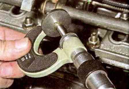
To do this, measure the thickness of the removed washer with a micrometer.
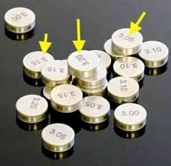
The thickness of the new shim is determined by the formula:
Н = В+(А — С), mm,
- where "A" is the measured gap; "B" - the thickness of the removed washer;
- "C" - nominal clearance; "H" is the thickness of the new washer.
The thickness of the new washer is marked on its surface with an electrograph.
We install a new washer in the pusher with the marking down and remove the retainer.
Check the gap again.
When properly adjusted, the 0.20 or 0.35 mm feeler gauge should fit into the gap with a slight pinch.
Sequentially turning the crankshaft half a turn, we check and, if necessary, adjust the clearances of other valves in the sequence indicated in the table.
We assemble the engine in the reverse order.
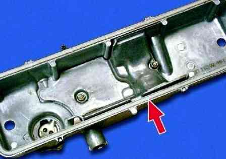
Before installing the block head cover, we replace its sealing gasket with a new one.


