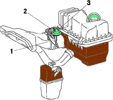
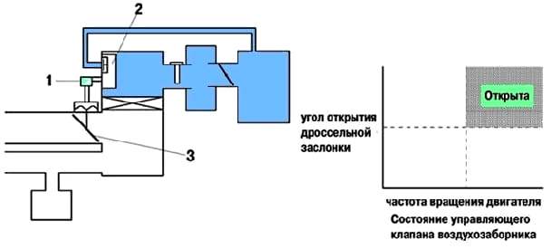
The air filter inlet is divided into two chambers, the air intake control valve and the actuator are installed in one of the chambers
The result is a reduction in intake noise in the low rpm range and an increase in power in the high rpm range.
When the engine is running in the low to medium speed range, the air intake control valve closes one chamber of the air filter inlet.

When the engine is running in the high speed range, the control system opens both chambers of the air filter inlet pipe using the air intake control valve.


