Checking and adjusting the wheel alignment is necessary to ensure good stability and controllability of the car, as well as for uniform tire wear during operation
Wheel alignment
- Cast angle of front wheels 2º40´±45´
- The angle of the transverse inclination of the axis of rotation of the front wheels 12º±45´
- Camber angle of the front wheels 0º30´±45´
- Rear camber -1º±45´
- Toe-in front wheels (0±2) mm
- Rear wheel toe-in (4±2) mm
The maximum difference between the angles of the right and left wheels is 45´
Wheel alignments should be checked with the vehicle unloaded, with the fuel tank half full, with normal tire pressures and no excessive play in the suspension units
After installing the car on the stand, immediately before checking the corners, "squeeze" the car's suspension, applying two or three times a force of 3922-490 N (40-50 kgf), directed from top to bottom, first to the rear bumper, and then to the front .
The wheels of the car must be parallel to the longitudinal axis of the car.
The camber angle is characterized by the deviation of the mean plane of wheel rotation from the vertical.
Toe-in is defined as the difference in the distances between the tread centers of the right and left tires behind and in front of the axis of rotation at a height equal to half the diameter of the wheel.
The angle of inclination of the axis of rotation of the front wheel is formed by a vertical line and a line passing through the middle of the upper support of the telescopic strut and the center of the sphere of the ball bearing mounted on the lower arm.
Projections of this angle onto the longitudinal and transverse planes represent the angle of longitudinal inclination of the axis of rotation and the angle of transverse inclination of the axis of rotation, respectively.
When checking and adjusting the front wheel alignment, first check the caster angle, then the camber angle, and finally the toe-in.
Toe-in of the front wheels is regulated by changing the length of the steering rods
The camber angle of the front wheels is adjusted by selecting according to special tables and replacing the bolts securing the steering knuckle to the shock absorber strut
Adjustment of the angle of inclination of the axis of rotation is not provided for by the design of the car
When checking and adjusting the rear wheel alignment, first check the camber angle, then the toe-in.
Toe-in of the rear wheels is adjusted by changing the length of the rear wishbones
Rear camber adjustment is not provided by the vehicle design
After adjusting the rear wheel toe-in, the difference between the lengths of the rear wishbones must not exceed 1.5 mm.
Checking and adjusting wheel alignment
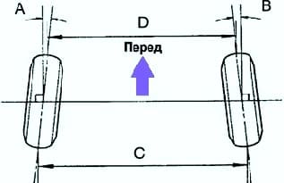
Check the toe angles (fig. 1).
If the angles of convergence do not correspond to the specified values, make an adjustment.
Convergence:
- A+B = 0°±0.2°;
- C–D = 0±2 mm.
Adjustment
Remove the clamps of the covers.
Loosen the lock nuts on the tie rod ends.
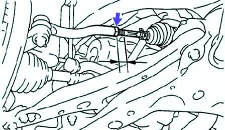
Adjust the toe angle by turning the left and right tie rods the same number of turns (fig. 2).
Try to set the angle of convergence to an average value.
Make sure that the lengths of the right and left rods are the same.
Difference in rod length: less than 1.5 mm.
Tighten the tie rod end locknuts. Tightening torque: 74 Nm.
Reinstall the covers and secure them with clamps.
Make sure the covers are not twisted.
Checking and adjusting wheel angles
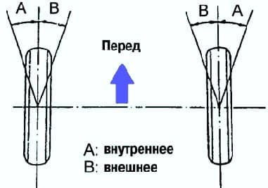
Check the steering angles of the wheels (fig. 3).
If the steering angles of the wheels differ from the standard, then you need to make sure that the lengths of the left and right steering rods are the same.
Checking the camber, pitch and roll of the steering axes
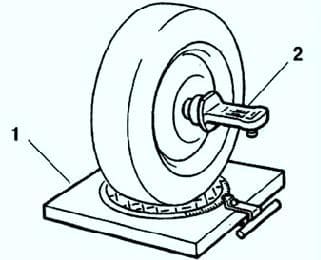
Check the camber of the front wheels, the longitudinal and transverse inclination of the steering axes (Fig. 4).
The longitudinal and transverse inclination of the axes of rotation of the front wheels is not adjustable, therefore, after adjusting the camber, if these values do not correspond to the specified conditions, it is necessary to check the condition and replace the faulty suspension parts.
Camber adjustment
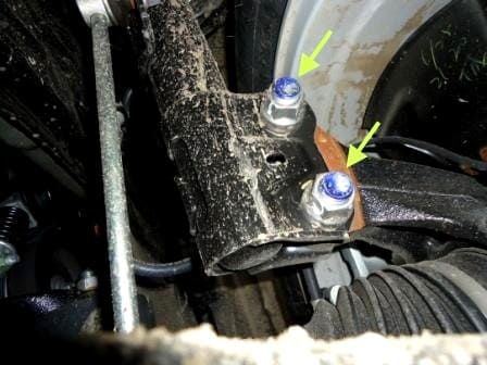
After adjusting the camber, check the toe angle of the front wheels again.
Remove the front wheels and the speed sensor (ABS) clamp.
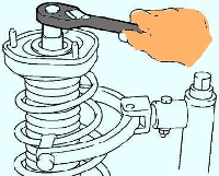
Remove the two fastening nuts from the underside of the rack (fig. 5).
Apply engine oil to the nut threads.
Temporarily install the nuts.
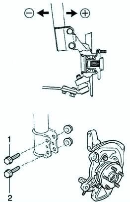
Adjust the amount of camber by moving the bottom of the post (fig. 6).
Set the camber to an average value.
When using a bolt without a mark, camber adjustment is possible in the range from 0°06 ’ to 0°30 ’ .
Tighten the nuts. Tightening torque: 211 Nm.
Install the front wheels. Tightening torque: 103 Nm.
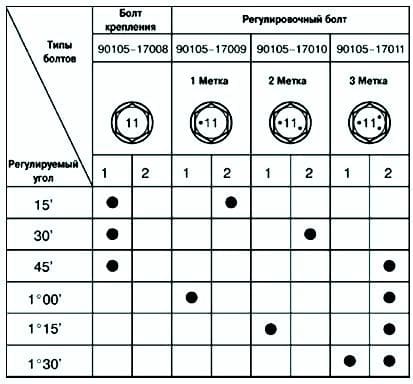
Check the camber.
If the camber does not meet the specified conditions, then use the table to select the bolt and adjust


