Disassembly and repair of the gearbox is required for the following faults.
1. Increased noise in the gearbox:
- - bearing wear;
- - wear of gear teeth and synchronizers;
- - axial movement of the shafts.
2. Difficult shifting:
- - wear of the spherical joint of the gear lever, lack of lubrication in the assembly;
- - deformation of the gear lever;
- - burrs, curvature, contamination of the sockets of the rods, jamming of the locking crackers;
- - pollution of the splines of the sliding sleeve and the hub;
- - deformation of the shift forks.
3. Spontaneous disengagement or fuzzy engagement of gears:
- - wear of holes for balls on rods, breakage of retainer springs;
- - wear of the synchronizer blocking ring;
- - failure of the synchronizer spring;
- - wear of the teeth of the synchronizer clutch or the synchronizer ring gear.
4. Low or leaking oil:
- - wear of the seals of the primary and secondary shafts;
- - loosening of the gearbox housing covers, damage to the gaskets;
- - loosening of the fastening of the clutch housing to the gearbox housing.
The listed malfunctions may be caused by other reasons, the elimination of which does not require the removal and disassembly of the gearbox.
You will need: screwdrivers (two), interchangeable heads “13”, “17”, extension cord, wrench, keys “10”, “13” (two), “17”, “19”, “30”, impact screwdriver, snap ring remover, hammer, universal pullers.
Drain the oil from the gearbox housing if you did not do so when removing it from the vehicle.
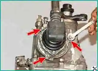
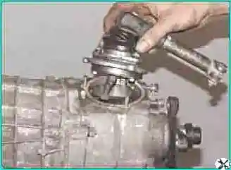
Remove the three nuts securing the gear selector housing and remove the selector mechanism.
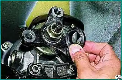
Remove the centering ring seal.
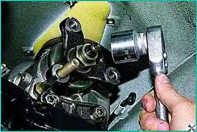
While holding the flexible coupling flange from turning, unscrew the flange fastening nut.
By unscrewing the nut, you simultaneously compress the centering ring from the secondary shaft.
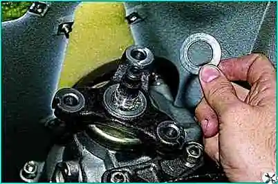
Remove the lock washer
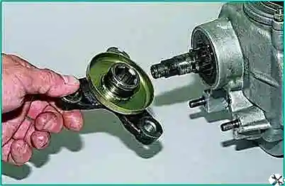
Remove the flexible coupling flange
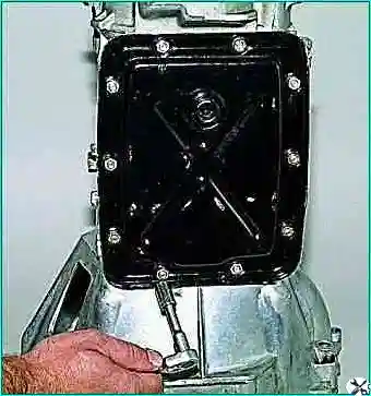
We install the gearbox with the clutch housing on the workbench. With a “10” head, we unscrew ten nuts securing the lower cover of the gearbox.
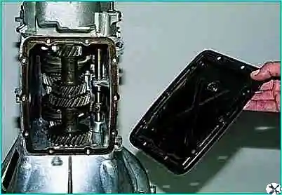
Remove the cover
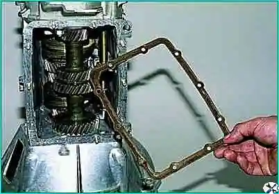
Remove the gasket.
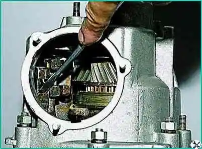
With a screwdriver, through the hole in the gear selection mechanism, we move down the stem of the fork of the I-II gears (this turns on the II gear).
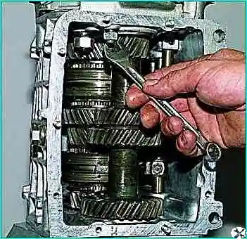
Using the “13” key, we unscrew the rear cover fastening nut located inside the box body
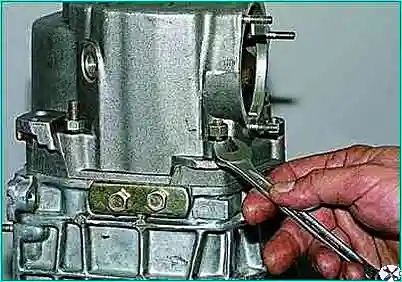
Using the “13” key, we unscrew the five nuts securing the rear cover located outside the case
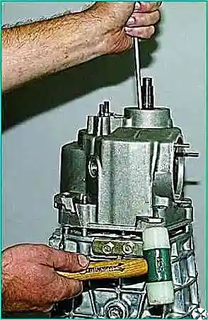
We tap the tides of the cover with a hammer, while using a screwdriver (or a suitable piece of pipe with the output shaft seal removed) we hold the rear bearing on the output shaft.
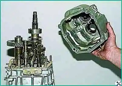
We shift the cover from the studs and remove it by turning it clockwise (looking from the side of the output shaft shank) to prevent the cover from touching the rods and the gear unit of the 5th gear and reverse.
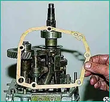
Remove the cover gasket
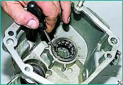
To replace the bearing of the gear unit of the V gear and reverse, pry off the bearing rollers with a screwdriver and remove the rollers from the cage
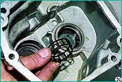
Retrieve the separator.
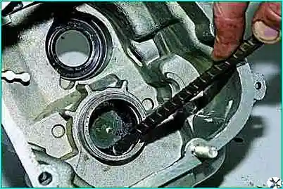
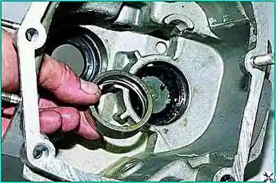
Hooking the outer ring of the bearing with a hook, we take it out of the socket of the rear cover.
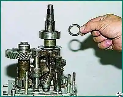
Remove the thrust ring of the rear bearing of the secondary shaft.
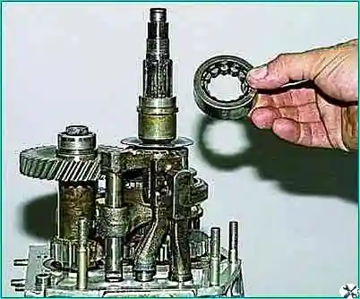
Remove the outer race of the bearing with cage and rollers
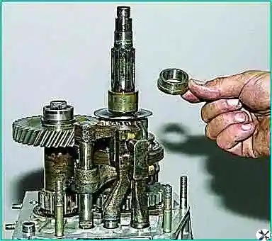
Remove the bearing inner race
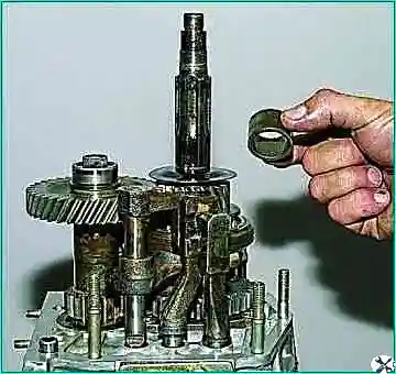
Remove the spacer
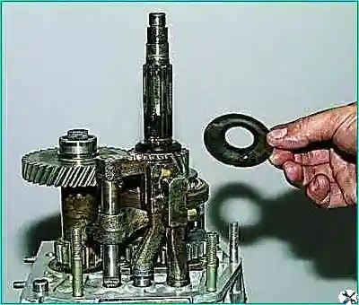
Remove the oil slinger.
To stop the shafts from turning, two gears must be engaged. II gear was engaged when the rear cover was removed.
Before engaging reverse or V gears, we release the fork for engaging these gears.
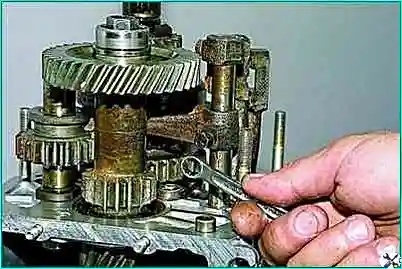
To do this, use the “10” key to unscrew the bolt securing the fork to the stem.
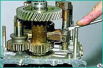
Pushing the plug down with a screwdriver, turn onwe accept reverse gear
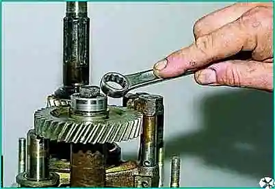
With a ring wrench (head) “by 17”, we unscrew the bolt securing the gear unit of the V gear and reverse gear.
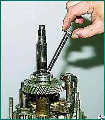
Remove the bolt
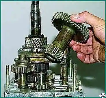
Remove the gear unit from the splines of the intermediate shaft.
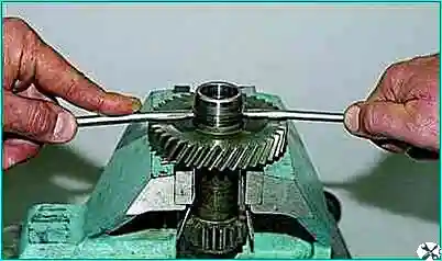
We clamp the V gear and reverse gear unit in a vise with soft metal jaw pads.
Using two screwdrivers, we press the inner ring of the gear block bearing
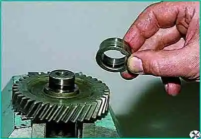
Remove the inner ring
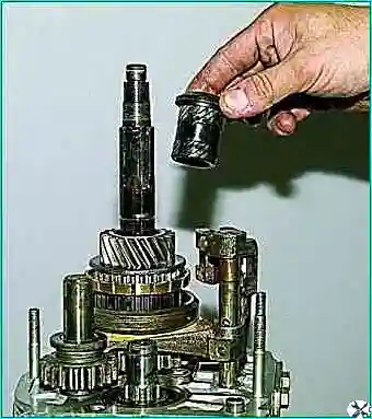
Remove the V gear bushing
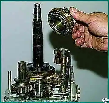
Remove the gear itself with the synchronizer blocking ring
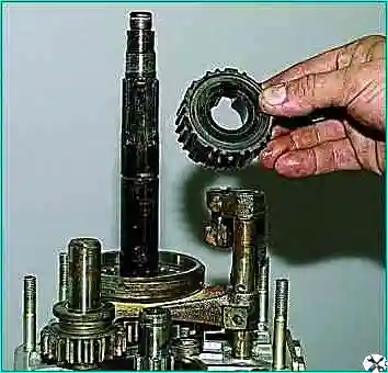
Remove the hub
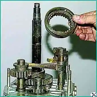
Remove the synchronizer clutch
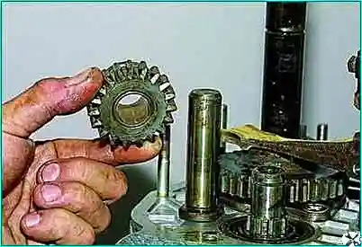
By turning the V gear and reverse fork on the rod to the output shaft, remove the reverse gear
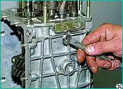
Using a 13" spanner, unscrew the two bolts securing the latch cover.
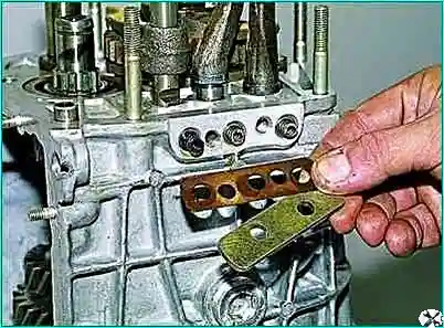
Remove the cover and gasket.
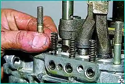
We take out the springs of the clamps (the spring of the rod of the V gear and reverse is longer than the other two and has a dark coating color)
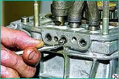
Use a magnetized screwdriver to remove all three latches.
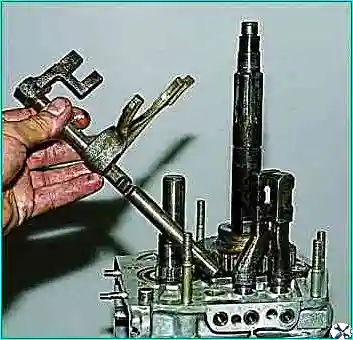
We take out the V gear and reverse gear engagement rod with a fork
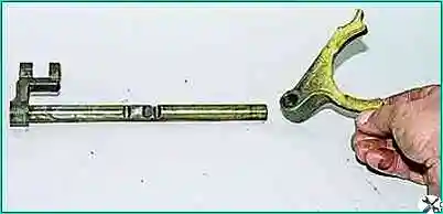
Remove the plug from the stem
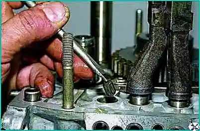
With a magnetized screwdriver, we remove the blocking cracker from the hole in the gearbox housing, which is located between the crankcase slots for the rods of the 5th gear and reverse gear and III–IV gears.
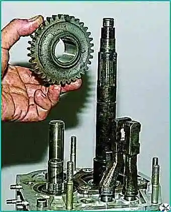
Remove the reverse driven gear from the secondary shaft.
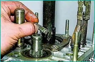
Remove the key from the groove of the shaft
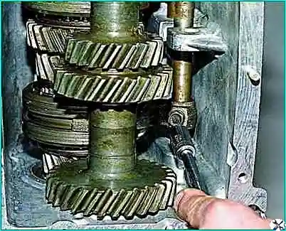
With a “10” head, we unscrew the bolt that fastens to the stem of the III-IV gear fork
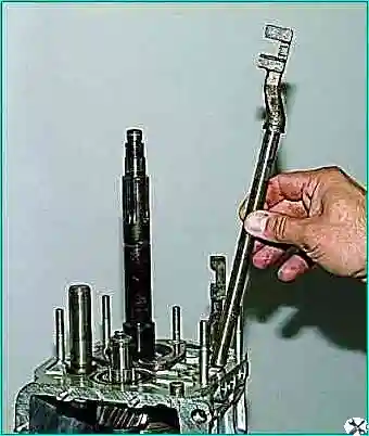
We take out the stem.
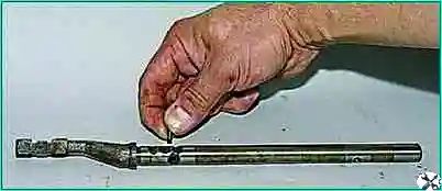
A blocking cracker is inserted into the hole of the rod, take it out.
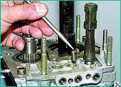
Using a magnetized screwdriver, we remove the blocking cracker from the hole in the gearbox housing, which is located between the crankcase slots for the rods of I–II and III and IV gears (this cracker is noticeably longer than the cracker located between the engagement rod for the V gear - reverse gear and the engagement rod for the III–IV gears).
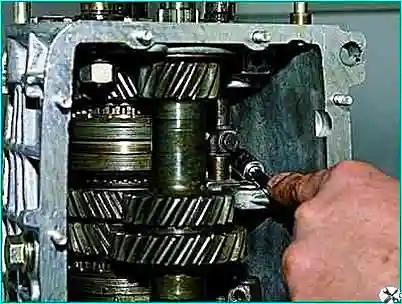
With a “10” head, we unscrew the bolt securing the I-II gear fork to the stem.
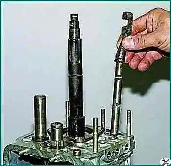
Removing the stem
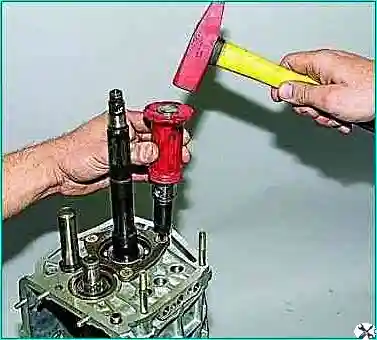
Using an impact screwdriver with a Phillips tip, we unscrew the three screws securing the locking plate of the intermediate bearing of the output shaft
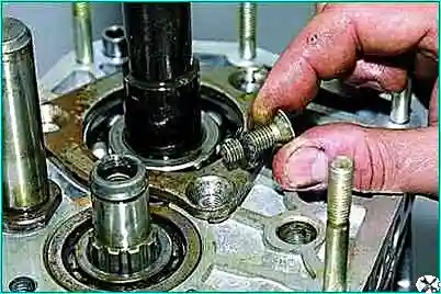
The screws are secured with special washers.
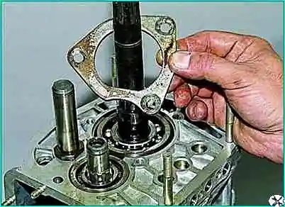
Remove the lock plate.
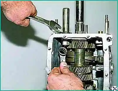
Using a 19 spanner wrench, unscrew the nut securing the reverse intermediate gear axle, holding the axle from turning with a 24 wrench
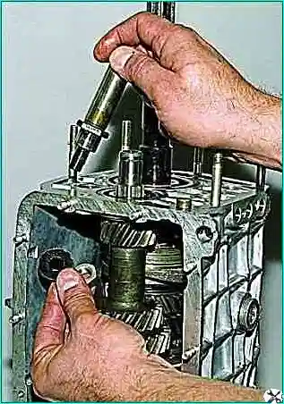
Remove the shaft of the reverse idler gear
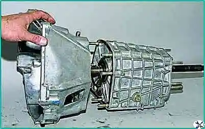
Having unscrewed the nuts securing the clutch housing, we separate the clutch and gearbox housings.
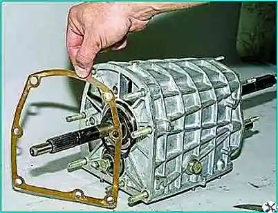
Cwe take the gasket.
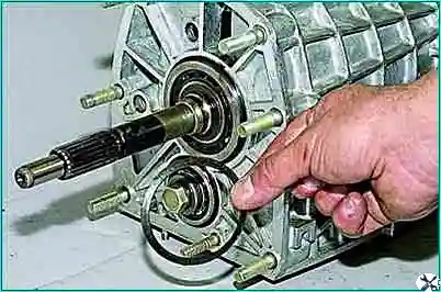
Remove the spring washer with a conical surface from the input shaft (with a smaller diameter it faces the bearing).
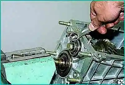
We clamp the splined part of the input shaft in a vice with soft metal jaws.
Using a “19” spanner, unscrew the bolt of the clamping washer of the front bearing of the intermediate shaft.
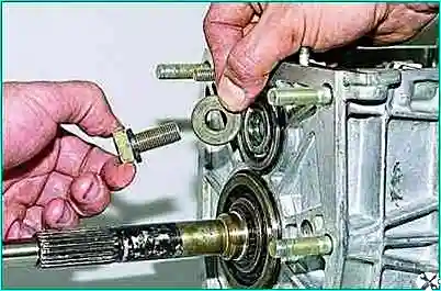
Remove the bearing clamp
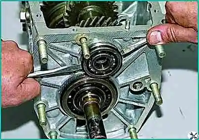
Using two screwdrivers, we pry the front double-row bearing of the intermediate shaft by the adjusting ring
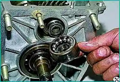
Remove the bearing.
When removing a bearing, its rear inner ring may remain on the shaft
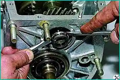
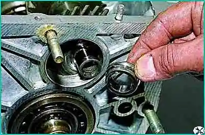
Using two screwdrivers, we press the rear inner ring of the bearing and remove it
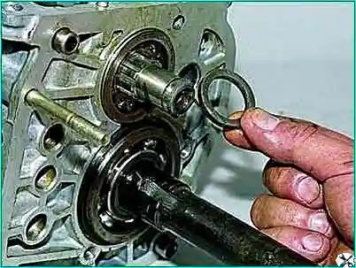
We take out the thrust ring of the rear bearing of the intermediate shaft
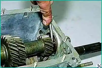
By inserting a screwdriver between the ends of the bearing and the gear of the 1st gear of the intermediate shaft, we move the rear bearing
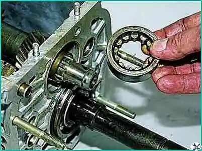
We take out the outer ring of the bearing with the cage and rollers.
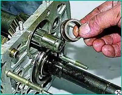
Remove the inner race of the bearing from the toe of the shaft.
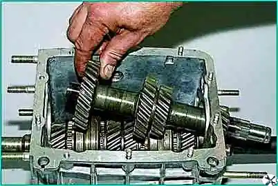
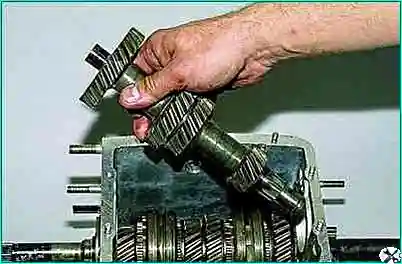
Sliding the intermediate shaft back, remove it from the gearbox housing.
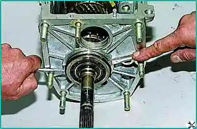
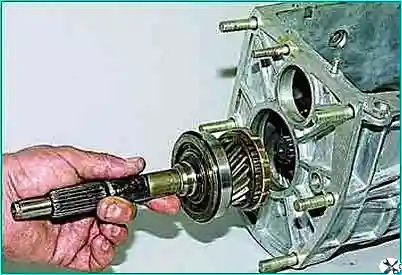
Prying off the rear bearing of the input shaft with two screwdrivers by the adjusting ring, we take out the input shaft assembly with the bearing and the synchronizer blocking ring.
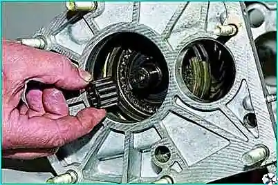
From the front toe of the secondary shaft, remove the needle bearing.
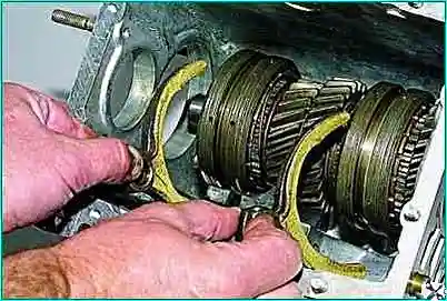
Remove the shift forks of 1st and 2nd, 3rd and 4th gears.
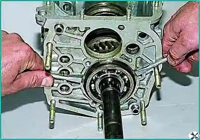
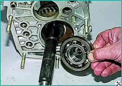
Using two screwdrivers, we pry the intermediate bearing of the secondary shaft by the adjusting ring and remove it.
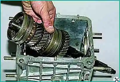
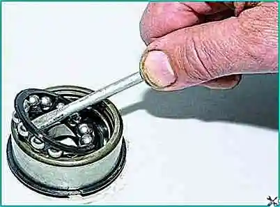
Tilting, we remove the secondary shaft assembly from the gearbox housing with gears, couplings, hubs and synchronizer blocking rings.
We assemble the gearbox in the reverse order.
If, when removing the front double-row intermediate shaft bearing, its rear inner ring remains on the shaft, then the bearing must be assembled before installation.
To do this, carefully remove the separator with balls from the outer ring of the bearing with a screwdriver and put it on the inner ring (removed from the shaft).
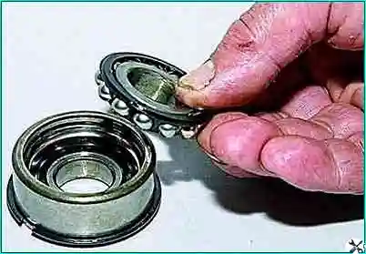
The cage with balls and the inner ring is inserted into the outer ring of the bearing.
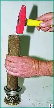
When assembling the input shaft with a suitable piece of pipe, we press the bearing onto the shaft, relying on its inner ring.
After installing the secondary and intermediate shafts into the gearbox housing, we press in the front and rear bearings of the intermediate shaft, the intermediate bearing of the secondary shaft and the inner ring of the gear block bearing.
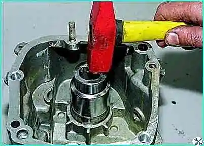
We press the outer ring of the bearing of the gear unit of the V gear and reverse gear with a tool head of a suitable size (a piece of pipe) into the socket of the rear cover.
Insert the separator and rollers into the outer ring of the bearing.
To prevent loosening of the bolt securing the gear unit of the 5th gear and reverse gear, we apply thread sealant to the thread of the bolt.
For ease of installation of the rear cover, we install the rear bearing assembly on the secondary shaft.
It is advisable to lubricate all gaskets with a thin layer of silicone sealant.
When assembling the gear selection mechanism, apply Litol-24 grease to the ball joint.
We look at the disassembly of the input and output shafts in the article - “Disassembly of the gearbox shafts”.


