The gearbox converts the torque transmitted from the engine in magnitude and direction
This is necessary to ensure optimal speed and cross-country ability of the car, high efficiency of the engine and reversing of the car
In addition, the gearbox separates the engine and transmission when the car is stopped and parked, as well as when it coasts with the engine running.
All manual transmission models are equipped with a 5-speed gearbox combined with a differential and final drive.
Torque from the engine is transmitted through the gearbox and final drive to the differential, which in turn distributes it between the drive shafts.
The five-speed manual transmission is equipped with a synchronization mechanism for all gears.
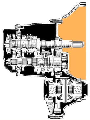
The 2AZ-FE engine is equipped with an E354 manual gearbox.
The basic design and operation of the E352 manual transaxle is the same as on the Previa / Tarago models.
The gear ratios have been changed to match the characteristics of the vehicle.
Triple-cone synchronizers are used in the 1st and 2nd shift mechanism to increase the load capacity of the synchronizer.
This reduces shifting effort and ensures smooth shifting.
A double cone synchromesh mechanism is used in the reverse gear engagement mechanism for smooth shifting.
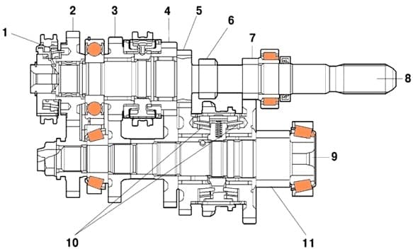
Fig. 2. The gearbox of the new Camry car: 1 - two-cone synchronizer (for reverse gear); 2 - gear wheel of the 5th gear; 3 - gear wheel of the 4th gear; 4 - gear wheel of the 3rd gear; 5 - gear wheel of the 2nd gear; 6 - reverse gear
On the output shaft of the gearbox is the main gear spur gear, driven gears and gear synchronizers
Pairs of forward gears are in constant mesh
The gears of the first and fifth gears in the neutral position rotate freely on the output shaft
Forward gears are engaged by axial movement of the corresponding synchronizer clutches mounted on the secondary shaft
Reverse gear is engaged by moving the reverse intermediate gear along its axis
The gearshift mechanism is located in the cover mounted on top of the gearbox housing
The gearbox control drive consists of a gear lever linkage with a ball bearing mounted on the base of the body, a system of rods and levers mounted on the bracket of the rear suspension support of the power unit and a mechanism installed in the gearbox housing
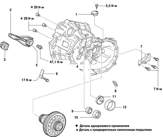
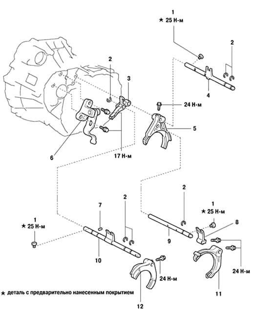
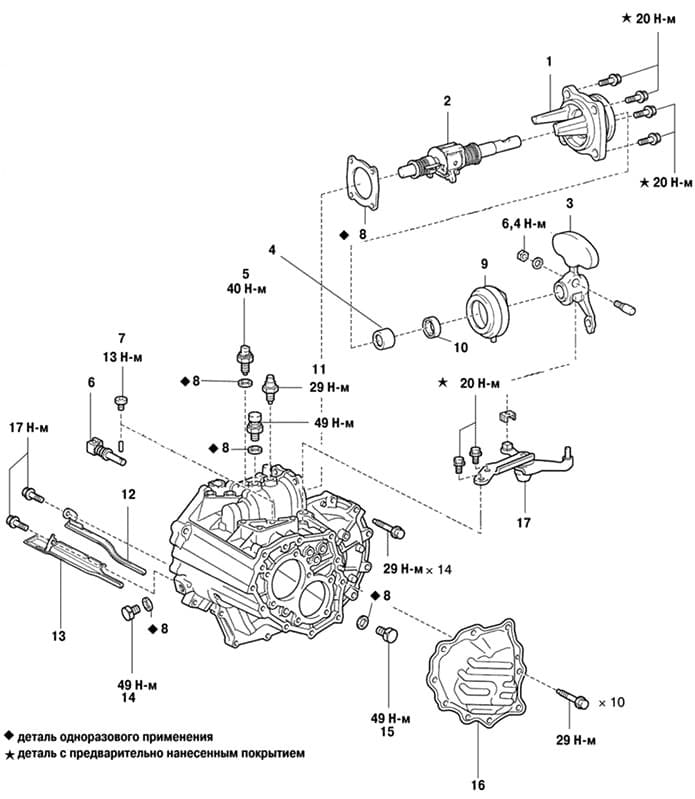
Manual transmission components in final drive
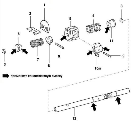
The components of a manual transmission are shown in the pictures:
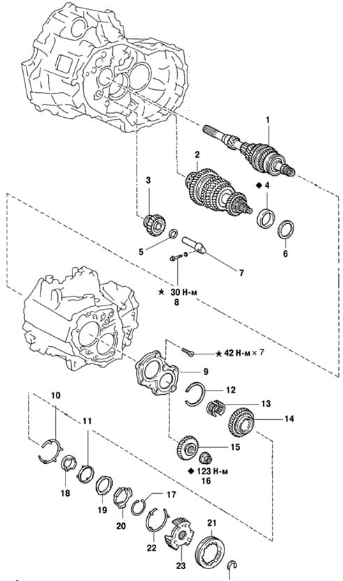
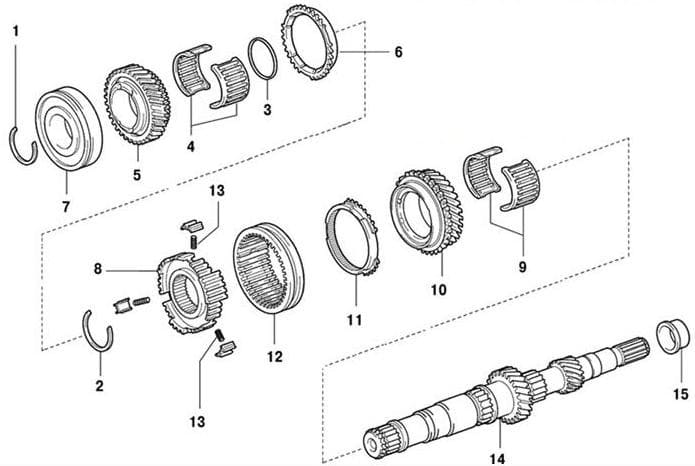
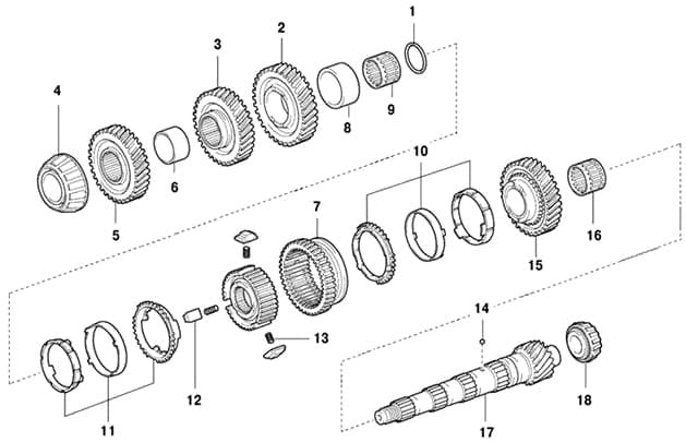
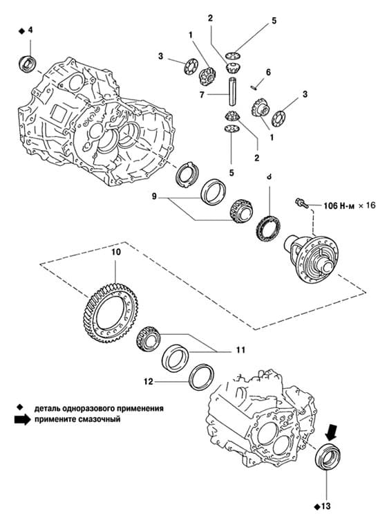
Possible malfunctions of a manual transmission and solutions
Vibration, noise in the gearbox
Loose or damaged engine and transmission mounts - tighten fasteners or replace mounts
Worn or damaged gears and bearings - repair gearbox
Wrong brand of oil filled - fill with correct brand of oil
Insufficient oil level - add oil to the correct level
Incorrect engine idle adjustment - adjust engine idle
Difficult shifting and grinding noise when shifting
Incomplete clutch disengagement - adjust clutch actuator
Incomplete fit or wear of the blocking rings and synchronizer cones - adjust the gearbox
Loose synchronizer springs - repair gearbox
Wrong brand of oil filled - change oil
Spontaneous disengagement
Worn shift forks or broken detent springs - repair gearbox


