Checking the electric lock on the front door on the driver's side
Check for signal continuity between the connector pins and the central locking switch in the positions shown in the table
|
Connector Pin# |
Switch position |
Inspection result |
|---|---|---|
|
5-8 |
LOCK |
Yes |
|
─ |
OFF |
No Conductivity |
|
6-8 |
UNLOCK |
None |
Also check that there is no conduction signal in the OFF position.
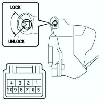
If the conductivity does not match the data in the table, replace the switch.
Check the operation of the driver's door lock electric drive in the positions indicated in the table.
Connect the positive battery terminal to the "4" terminal and the negative terminal to the "1" terminal, make sure that the lock latch is in the LOCK position.
Reverse the polarity of the connector pins and make sure the lock latch is in the UNLOCK position.
If the operation of the electric drive does not match, replace the lock.
|
Polarity |
Action |
|---|---|
|
Battery (+) - pin 4 Battery (─) - Pin 1 |
LOCK |
|
Battery (+) - pin 1 Battery (─) - Pin 4 |
UNLOCK |
Check for signal continuity between the terminals of the connector and the door lock switch on the driver's side in the positions indicated in the table.
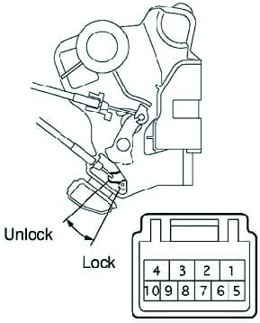
If the conductivity does not match the data in the table, replace the lock assembly.
|
Connector Pin# |
Switch position |
Inspection result |
|---|---|---|
|
7-8 |
LOCK |
No Conductivity |
| < |
UNLOCK |
conductivity |
Checking the electric lock on the passenger side front door
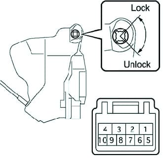
Check for signal continuity between the connector pins and the central locking switch in the positions indicated in the table.
Also check that there is no conduction signal in the OFF position.
If the conductivity does not match the data in the table, replace the switch.
|
Connector Pin# |
Position switch |
Inspection result |
|---|---|---|
|
9-7 |
LOCK |
Yes |
|
─ |
OFF |
No Conductivity |
|
10-7 |
UNLOCK |
None |
Check the operation of the electric drive of the passenger door lock in the positions indicated in the table.
By connecting the positive battery terminal to the "4" terminal and the negative terminal to the "1" terminal, make sure that the lock latch has moved to the "LOCK" position.
Reverse the polarity of the connector pins and make sure the latch is in the "UNLOCK" position.
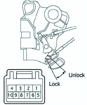
If the operation of the actuator is not as described, replace the lock assembly.
|
Polarity |
Action |
|---|---|
|
Battery (+) - pin 4 Battery (─) - Pin 1 |
LOCK |
|
Battery (+) - pin 1 Battery (─) - Pin 4 |
UNLOCK |
Check for continuity between the connector pins and the passenger side door lock switch at the positions shown in the table.
If the conductivity does not match the data in the table, replace the lock assembly.
|
Pin# connector |
Position switch switch |
Inspection result |
|---|---|---|
|
7-8 |
LOCK |
No Conductivity |
|
UNLOCK |
conductivity |
Checking the electric lock of the rear right door
Check the operation of the rear right door lock electric drive in the positions indicated in the table.
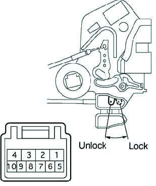
By connecting the positive battery terminal to the "4" terminal and the negative terminal to the "1" terminal, make sure that the lock latch has moved to the "LOCK" position.
Reverse the polarity of the connector pins and make sure the latch is in the "UNLOCK" position.
If the operation of the actuator is not as described, replace the lock assembly.
|
Polarity |
Action |
|---|---|
|
Battery (+) - pin 4 Battery (─) - Pin 1 |
LOCK |
|
Battery (+) - pin 1 Battery (─) - Pin 4 |
UNLOCK |
If the conductivity does not match the data in the table, replace the lock.
|
Pin# connector |
Position switch |
Inspection result |
|---|---|---|
|
6-9 |
LOCK |
No Conductivity |
|
UNLOCK |
conductivity |
Checking the electric lock of the rear left door
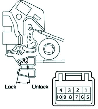
Check the operation of the rear left lock electric drive in the positions indicated in the table (Fig. 6).
By connecting the positive battery terminal to the "4" terminal and the negative terminal to the "1" terminal, make sure that the lock latch has moved to the "LOCK" position.
Reverse the polarity of the connector pins and make sure the latch is in the "UNLOCK" position.
If the operation of the actuator is not as described, replace the lock assembly.
|
Polarity |
Action |
|---|---|
|
Battery (+) - pin 4 Battery (─) - Pin 1 |
LOCK |
|
Battery (+) - pin 1 Battery (─) - Pin 4 |
UNLOCK |
Check for signal continuity between the connector pins and the rear left door lock switch in the positions shown in the table.
If the conductivity does not match the data in the table, replace the lock assembly.
|
Output number connector |
Position switch |
Result Checks |
|---|---|---|
|
6-9 |
LOCK |
No conductivity |
|
UNLOCK |
conductivity |
Checking the electric tailgate lock
Check the operation of the tailgate lock electric drive in the positions indicated in the table.
By connecting the positive battery terminal to the “1” terminal and the negative terminal to the lock body, make sure that the lock latch has moved to the “Open” position.
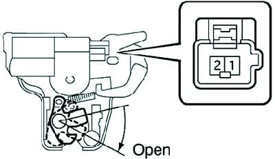
If the operation of the actuator is not as described, replace the lock assembly.
|
Polarity |
Action |
|---|---|
|
Battery (+) - pin 1 Battery (─) - lock body |
Open |


