The car uses DC electrical equipment with a nominal voltage of 12 V
The electrical equipment of the car is made according to a single-wire circuit - the negative terminals of sources and consumers of electricity are connected to the "ground", which acts as a second wire. In turn, the role of the "mass" is performed by the body of the car.
Most circuits are turned on by the ignition switch.
Always on (regardless of the position of the key in the ignition switch): car anti-theft warning lamp, door lock, high beam alarm, brake lights, exterior lighting, interior and individual lighting domes, emergency alarm, horn and engine compartment lamp.
When the engine is off, the switched on consumers are powered by the battery, and after starting - from the generator.
When the generator is running, the battery is charged. The car is equipped with a lead starter battery 6 ST-55 AZ.
Generator 9402.3701-04 is a synchronous AC machine with electromagnetic excitation with built-in rectifier unit and voltage regulator.
The rated output current of the generator is 80 A at a voltage of 14 V and a rotor speed of 6000 min -1. The generator rotor is driven by a V-ribbed belt from the accessory drive pulley on the engine crankshaft.
The stator and generator covers are held together with four bolts.
The back of the generator is covered with a plastic casing.
The rotor shaft rotates in two ball bearings installed in the generator covers.
Enclosed type bearings, the grease in them is designed for the entire life of the generator.
The rear bearing is pressed onto the rotor shaft, installed in the rear cover in a plastic sleeve.
The front bearing is pressed into the front cover of the generator, the bearing has a sliding fit on the rotor shaft.
Three-phase windings are located in the generator stator.
The ends of the phase windings are soldered to the terminals of the rectifier unit, consisting of six silicon diodes (valves) - three positive and three negative, pressed into two horseshoe-shaped aluminum holder plates in accordance with the polarity (positive and negative - on different plates).
The plates are fixed on the rear cover of the generator (under the plastic casing).
The excitation winding is located on the generator rotor, its leads are soldered to two copper slip rings on the rotor shaft.
Power to the excitation winding is supplied through two brushes located in the brush holder, which is structurally integrated with the voltage regulator and fixed on the rear cover of the generator. The voltage regulator is a non-separable unit; in case of failure, it is replaced.
To protect the on-board network from power surges during the operation of the ignition system and to reduce interference with radio reception, a 2.2 microfarad capacitor is connected between the terminals of the "positive" and "negative" valves (between the "+" and "ground" of the generator).
When the ignition is turned on, the voltage to the excitation winding of the generator (terminals D of the generator and the “+” of the voltage regulator) is supplied through a circuit that includes a signaling device in the instrument cluster (the signaling device is on).
After starting the engine, the field winding is powered by the diodes of the rectifier unit (the signaling device goes out).
If the warning light comes on after starting the engine, this indicates a malfunction of the generator or its circuits. The "minus" of the battery should always be connected to the "mass" of the car, and the "plus" - to the terminal B + of the generator.
Reverse connection will lead to a breakdown of the diodes of the rectifier unit.
Starter 21214-3708010-01 is a 4-brush, permanent magnet-excited DC motor with planetary gear, freewheel roller clutch, and 2-winding traction relay.
Six permanent magnets are attached to the steel housing of the starter. The body and covers of the starter are tightened with two bolts. The armature shaft rotates on two bearings. A ball bearing is installed on the collector side, and a plain bearing on the drive side.
The torque from the armature shaft is transmitted to the drive shaft through a planetary gearbox, consisting of a central and crown (with internal gearing) gears and three satellites on the carrier (drive shaft).
A freewheel clutch (overrunning clutch) with a drive gear is installed on the drive shaft.
It transmits torque in only one direction - from the starter to the engine, disengaging them after starting the engine. This is to protect the starter from damage due to overspeed.
The traction relay is used to engage the drive gear with the ring gear of the engine crankshaft flywheel and turn on the power to the starter motor.
When the ignition key is turned to the "starter" position, voltage is supplied to the both windings of the traction relay (retracting and holding).
The relay armature retracts and moves the drive lever, which moves the freewheel with the drive gear along the splines of the drive shaft, engaging the gear with the flywheel crown. At the same time, the retracting winding is turned off, and the contacts of the traction relay are closed, including the starter motor.
After the key is returned to the "ignition" position, the holding winding of the traction relay is de-energized, and the relay armature returns to its original position under the action of the spring - the relay contacts open and the drive gear disengages from the flywheel. A defective traction relay is replaced.
A malfunction of the starter drive is detected during inspection after disassembling the starter.
The lighting and signaling system includes two headlights; side direction indicators; rear lights; license plate lights; additional brake signal; ceiling lamps for interior lighting, trunk and glove box, as well as a sound signal.
The headlight unit is equipped with an H7 low beam halogen lamp, an H1 halogen high beam lamp, a W5W side light lamp, a PY21W direction indicator lamp (orange) and an actuator (gear motor) for headlight beam direction control.
When the headlights are switched on, the low beam lamps are lit, and when the high beam is switched on, the high and low beam lamps are lit.
The car is equipped with a headlight range control with an electromechanical drive, which allows you to adjust the direction of the light beams depending on the load of the car.
The headlight corrector consists of a regulator on the instrument panel, gearmotors installed in the headlights, and connecting wires.
Some cars are equipped with fog lights, which are installed in the front bumper.
The fog lights use H11 halogen bulbs. The direction of the fog light beam is adjusted by a screw.
In the rear light there are lamps: brake light P21W, direction indicator PY21W (orange), fog and clearance light P21/4W, reversing light R10W.
The vehicle's electrical equipment includes a remote control unit for the electrical package.
The unit controls the locking (unlocking) of all doors, including the tailgate, turning on (off) the car security mode, turning on (off) the alarm mode when the car security zones are violated.
The locks of all doors are blocked by electric drives that are attached to the lock levers.
The car is equipped with power windows on the front doors. The power window gear motor consists of a worm gear and a reversible DC motor.
A drum with a cable is installed on the output shaft of the gearbox. A slider is fixed on the cable, moving along the guide. The glass holder is attached to the slider with two bolts.
The windshield wiper is installed under the windshield trim.
The cleaner motor is three-brush, two-speed, with permanent magnet excitation. To protect against overloads, a thermal bimetallic fuse is installed in it.
The windshield washer consists of a polyethylene tank with an electric pump, nozzles on the hood and connecting hoses.
The washer reservoir is installed on the right in the engine compartment.
The tailgate glass cleaner consists of a geared motor, a lever and a brush.
The cleaner motor is a two-brush type with permanent magnet excitation.
To protect against overloads, it has a thermal bimetal fuse.
The tailgate glass washer consists of a polyethylene tank in which an electric pump is installed, nozzles on the tailgate and connecting hoses.
The tailgate glass cleaner and washer are installed inside the tailgate. Most electrical circuits are protected by fuses.
Powerful consumers (headlights, cooling fan motors, fuel pump, etc.) are connected via relays.
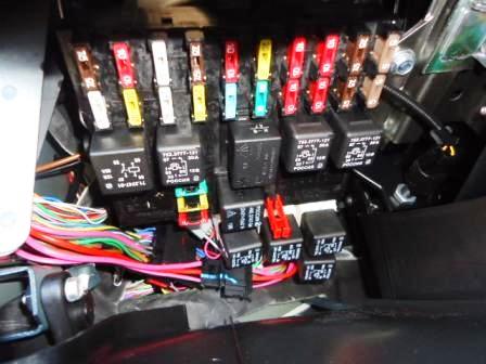
Most of the fuses and relays are located in the mounting block located in the passenger compartment under the instrument panel, to the left of the steering column.
The fuse and relay sockets are marked on the body of the mounting block.
The engine management relay and fuse box is attached to the controller bracket.
On a vehicle with air conditioning, the fuse (10 A) and the air conditioning compressor relay are installed on the left pillar of the instrument panel cross member and are covered by the instrument panel console screen.
From the Euro-5 version, the fuse box and the SUD relay are installed behind the instrument panel near the mounting block.

In the table. 1 gives the value of each fuse, but some of the circuits shown in the table may not be available on a particular car model.
Fuse-protected circuits
Designation Current (A) Protected elements
- F1 (5) License plate lamps, position lamps in the left headlight and left rear lamp, engine compartment lamp, parking light indicator lamp
- F2 (7,5) Low beam lamp (left headlight)
- F3(10) High beam lamp (left headlight), headlight high beam warning lamp
- F4(10) Left fog light
- F5(30) Power window relay, front power windows
- F6(15) Cigarette lighter
- F7(20) Horn relay, horn, trunk light
- F8(25) Back door window defroster, back door window defroster relay, exterior mirror defrosters
- F9(20) Heated back door glass switch, windshield wiper relay, windshield wiper motor, windshield washer pump, right hand stalk, glove box lamp, reversing lamps
- F10(20) Electric package remote control (door lock)
- F11(5) Side light bulbs in right headlight and right rear light, instrument illumination dimmer
- F12(7,5) Dipped beam bulb (right headlight), headlight beam dimmer gear motors
- F13(10) High beam lamp (right headlight)
- F14(10) Right fog light
- F15(20) Exterior mirror control unit, electric exterior mirrors, seat heating control unit
- F16(10) Turn signal/alarm relay-interrupter (in alarm mode)
- F17(7,5) Interior lamps, anti-theft warning lamp, brake lights, auxiliary brake light
- F18(25) Heater fan
- F19(10) Turn signal/alarm breaker relay (in turn signal mode), instrument cluster (except engine management system malfunction indicator lamp), starter relay
- F20(7,5) Rear fog lights, anti-theft control unit, buzzer


