")
")
")
")
")
")
Checking the front door speaker
Check the resistance between the front door speaker leads.
If the resistance is not correct, replace the front door speaker
Resistance: 4 Ohm.
Connect a 1.5V battery to the front door speaker and check that the front door speaker makes sound.
If no sound is heard, replace the front door speaker.
Checking the front tweeter
Check the resistance between the front tweeter leads.
If the resistance is not correct, replace the front tweeter. Resistance: 3.2 Ohm.
Connect a 1.5V battery to the front tweeter and check that the speaker makes sound.
If no sound is heard, replace the front tweeter.
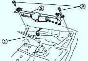
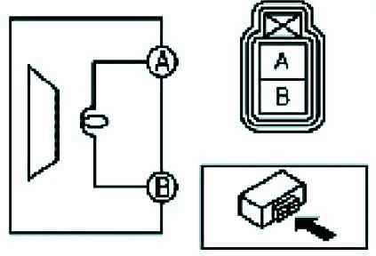
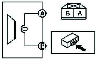
Checking the antenna feeder
Check that there is no electrical connection between terminals A and B of the antenna using an ohmmeter.
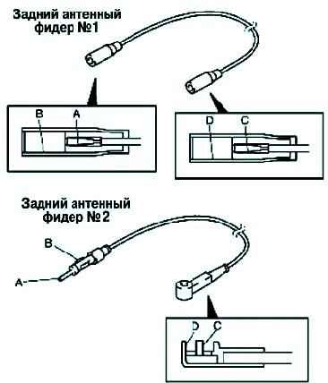
Check the resistance.
If the measurements do not match the data shown in Figure 4, replace the antenna feeder No. 1 or No. 2
Checking the audio control switch
Disconnect the negative cable from the battery.
Remove the driver's airbag module. Disconnect the audio control switch connector.
Check the resistance and continuity between the terminals of the audio control switch.
If the resistance is not as shown in the table, replace the sound system control switch.
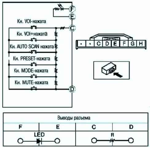
Resistance
Switch position - Resistance, Ohm
- VOL button pressed 51-56
- VOL button+pressed 140-154
- AUTO SCAN button pressed 285-315
- PRESET button pressed 534-589
- MODE button pressed 985-1,080
- MUTE button pressed 1,940-2,130
- Disabled 4,800-5,290
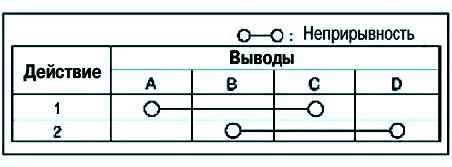
Checking the power window motor
Apply voltage to the positive battery terminal and connect the power window motor leads E and F to ground, then test the power window motor for operation.
If the operation of the power window motor is different from what is shown in the table, replace the wiper motor.
|
Work |
Output |
|
|---|---|---|
|
Front: F/Rear: E |
Front: E/Rear: F |
|
|
Opening |
GND |
B+ |
|
Closing |
B+ |
GND |
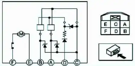
Apply voltage from the positive battery terminal at terminal D of the power window motor, terminal C connect to ground.
With the power window motor running, measure the voltage at terminals A and B.
If faulty, replace the power window motor.
Voltage:
Impulse: max.-12V, min.-0V.
Checking the Power Window Master Switch
Measure the voltage on all pins (except pins H and I).
If the voltage differs from the voltage shown in the table, check the items listed in the "Items to be tested" column and the corresponding wiring harnesses.
Disconnect the negative cable from the battery.
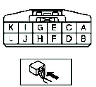
Check the power window master switch connector for continuity between terminals H and I.
If the system does not operate properly even if the components or related wiring harnesses are normal, replace the power window master switch.
Checking the Power Window Switch
Measure the voltage at the pins (except pins G and H).
If the voltage differs from the voltage shown in the table, check the items listed in the "Items to be tested" column and the corresponding wiring harnesses.
Disconnect the negative cable from the battery.
Check the power window switch connector for continuity between terminals G and H.
If the system does not operate properly even if the components or related wiring harnesses are normal, replace the power window switch.
Checking the rear window heating filament
Set the ignition switch to the ON position.
Turn on the rear window defroster.
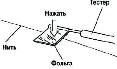
Touching the rear window heating filament with the probe of the tester may damage the filament.
Wrap aluminum foil around the end of the probe and test the thread by touching it with the foil (fig. 8);
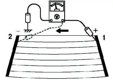
Connect the positive tester probe to the positive end of each thread, and the negative probe to the body ground (fig. 9);
By moving the positive probe from the positive end of the thread to the negative end, make sure that the voltage decreases accordingly.
If the voltage changes rapidly, the filament is faulty. Repair the thread.
Checking the electric exterior mirrors
Apply voltage from the positive battery terminal to the motorized exterior mirror terminals and check its operation.
If the test results are not correct, replace the power outside mirror.
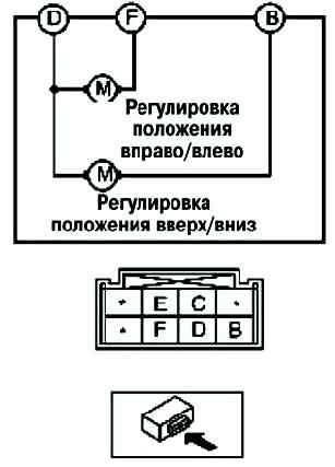
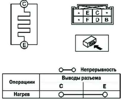
Check continuity between motorized exterior mirror heater terminals
Work - pin (B+) - GND:
- - up B - D;
- - down D - B;
- - left F - D;
- - right D - F
If the test results are not correct, replace the power outside mirror.
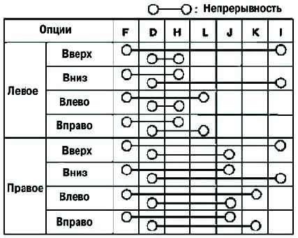
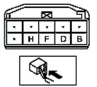
Checking the power door mirror switch
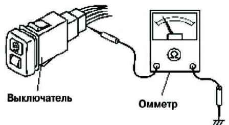
Check continuity between the power door mirror switch terminals using an ohmmeter.
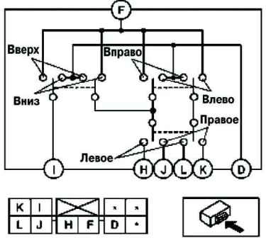
If the test is not correct, replace the power door mirror switch
Checking the lock and the rear door lock actuator
Apply voltage to the positive battery terminal and ground the corresponding terminals of the door lock actuator and check its operation.
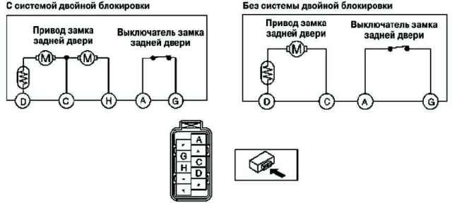
If the test results are not correct, replace the rear door lock and actuator.
Checking the lock and the front door lock actuator
Apply voltage to the positive battery terminal and ground the corresponding terminals of the door lock actuator and check its operation.
|
Actuator operation |
connection |
|
|---|---|---|
|
B+ |
GND |
|
|
Double block |
H |
LH:C RH:D |
|
Locked |
LH:D RH:C |
LH RH |
|
Unlocked |
LH;C RH:D |
LH;D RH;C |
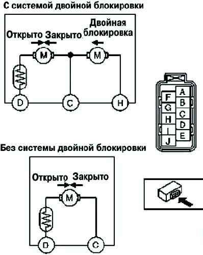
If the test results are not correct, replace the rear door lock and actuator.
Checking the lighting control switch on the instrument panel
Measure the voltage on all pins (except pin D).
If the voltage differs from that specified in the table, check the items listed in the "Items to be tested" column and the corresponding wiring harnesses.
Disconnect the light control switch connector on the instrument panel.
Verify that the continuity on pin D matches that shown in the pin voltage table.
If the voltage differs from that specified in the table, check the items listed in the "Items to be tested" column and the corresponding wiring harnesses.
If the system does not operate properly even if the components or associated wiring harnesses are good, replace the instrument panel light control switch.
Checking conclusions H
Check the waveform at the instrument panel light control switch terminals H with a tester (fig. 17)
Turn the light switch to TNS or ON.
Check that the resistance changes smoothly when turning the instrument panel lighting control switch from the maximum brightness position to the minimum brightness position.