")
")
")
")
")
")
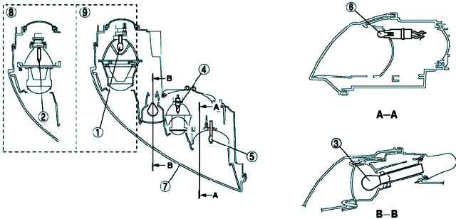
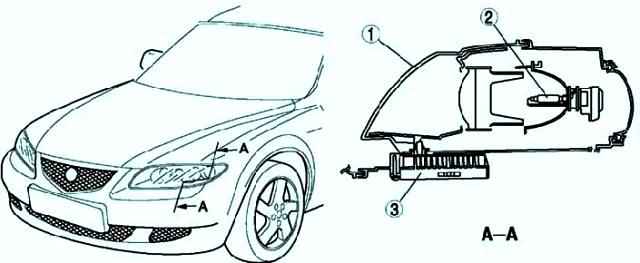
Mazda 3 Headlight Unit
Projector-type headlamps (low beam) and front fog lamps are used.
Headlights combined with front direction indicators and side lights into a single element to reduce size
Discharge headlights are used, giving a wide area of illumination and white light, close in spectrum to the sun (for vehicles equipped with gas discharge headlights).
Discharge headlight
Compared to modern headlights, the area of illumination is increased.
In addition, white light, close in spectrum to sunlight, provides better visibility when driving at night.
The use of a gas discharge headlight lamp gives high efficiency with low power consumption.
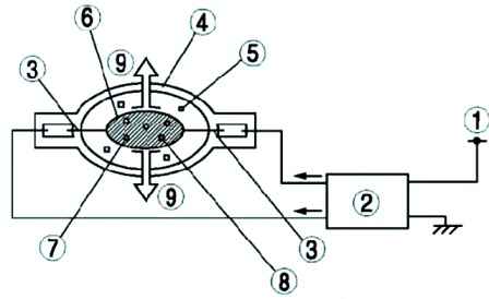
Design and operation of a gas discharge headlight
A high voltage pulse (approximately 25,000 volts alternating current) from the control unit of a gas discharge headlamp is applied between the terminals of its lamp, initiating a gas discharge in the xenon with which the lamp is filled.
When the xenon is energized, the temperature inside the HID headlight bulb rises, evaporating the mercury and causing an electric arc.
The mercury and the electric arc cause the temperature inside the lamp to rise further, the iodide evaporates and decomposes, the metal atoms release their stored energy, producing light.
Fault detection function
Input voltage drop detection function
If the input voltage of the gas discharge headlight control unit (9-16 V) is less than normal (except for the voltage drop immediately after the headlight is turned on), the control unit turns off the gas discharge headlights for protection.
The control unit for the gas discharge headlight switches the headlights on again when the normal operating voltage is restored.
Input fault detection function
If an abnormality is detected at the output of the system (open or short circuit in the wiring harness circuit), the control unit turns off the discharge headlights.
If the control unit for the gas discharge headlight has been triggered due to system output deviations, the headlights remain off until the headlight switch is turned back on to turn on the headlights.
Auto headlight leveling system
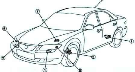
Automatic headlight leveling system (fig. 4)
The optical axes of the headlights are automatically set at certain angles to improve visibility and prevent dazzling drivers of oncoming vehicles when changing speed or vehicle load.
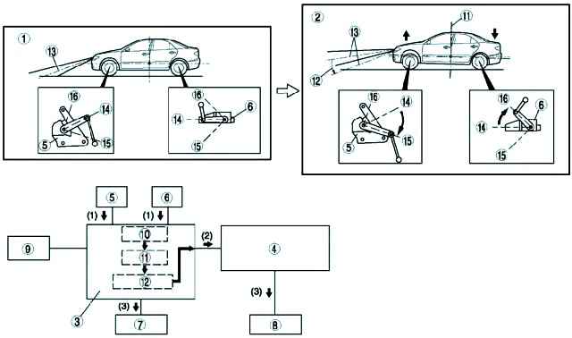

Work when the vehicle load changes
- 1. According to the vibrations of the suspension, the auto leveling sensors installed at the front and rear of the vehicle send a signal to the auto leveling control unit (master).
- 2. When a difference is detected between the two auto leveling sensor signals, the auto leveling control unit (main) checks the vehicle height, and then calculates the amount of optical axis adjustment and sends a signal to the auto leveling control unit (secondary).
- 3. The auto leveling control unit compares the actual and set position of the reflector and then outputs a control signal to the headlight leveling actuator.
Work while driving
- 1. When driving with the headlights on, the auto-levelling control unit (master) receives the vehicle speed signal from the ABS/TCS HU/CM or DSC HU/CM unit and the suspension vibration-based signal from the front and rear auto-leveling sensors as input.
- 2. Based on the vehicle speed signal, the auto leveling control unit calculates the acceleration angle and checks the change in vehicle speed.
In addition, if there is a difference between the two signals of the front and rear auto leveling sensors, the auto leveling control unit (master) checks the actual position of the vehicle.
The same unit calculates the amount of adjustment of the optical axis based on these two signals and outputs a signal to the auto-leveling control unit (optional).
- 3. The auto leveling control unit compares the actual and set position of the reflector and then outputs a control signal to the headlight leveling actuator.
When the ignition key is turned to the ON position, the sound of the headlight leveling actuator may be heard for a few seconds, this is normal as the system is being tested for operational status.
When driving on a bad or uneven road, the auto leveling function would cause a flickering effect, resulting in dazzling oncoming drivers.
To prevent this, the automatic headlight alignment is delayed.
Lighting control system while driving
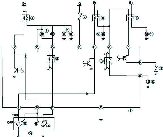
The driving light control system automatically controls the operation of the dipped beam headlights and TNS when the ignition is turned off using a special unit.