Air filter
The car is equipped with an air filter that can deodorize the air and purify it from pollen and dust.
The air filter consists of a deodorizer surrounded by a dust filter.
The deodorizer removes aldehyde containing odors, the dust filter traps small particles and suspension.
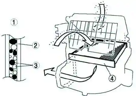
The air filter cannot be reused and must be replaced periodically.
Air conditioning unit
The air conditioning unit combines cooling and heating units.
Heater control damper operation
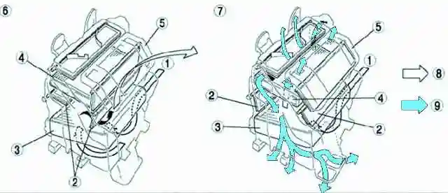
The heater control damper installed in the air conditioning unit controls hot or cold air, depending on the position of the temperature control.
Air temperature is controlled by changing the distribution of air flows.
Blower control damper operation
The blower control damper can be set to one of the following positions: Vent, BI-Level, Heat, Heat/Def or Defroster, depending on the position of the blower control.
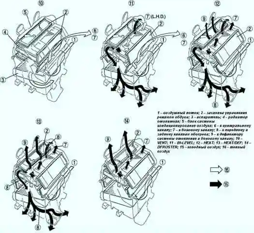
As a result, the air distribution mode changes.
Evaporator
A new type of evaporator is used, which combines a multi-flow evaporator (consisting of a condensing element and a subcooling element) and a gas-liquid separator (modulator).
The evaporator body is coated with a polymer that contains an antibacterial agent to eliminate the source of unpleasant odor and the spread of bacteria.
The placement of the tanks at the top and bottom of the evaporator block, as well as the internal design of the plates, made it possible to ensure the following:
- – improved heat transfer efficiency;
- – the temperature distribution has become more uniform;
- – the vaporizer has become thinner.
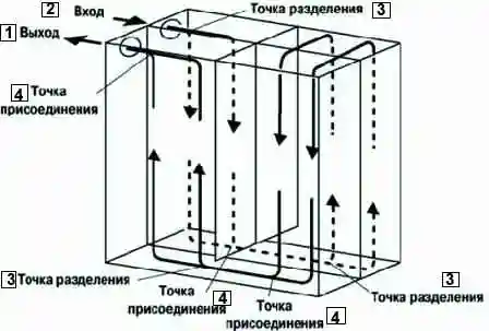
In the adopted pre-cooling cycle, after the refrigerant passes through the evaporator condensing element, the liquid and gaseous refrigerants that could not be liquefied are cooled again in the subcooling element.
Thus, the refrigerant is sent to the evaporator in an almost completely liquefied state.
Expansion valve
The expansion valve provides a rapid reduction in liquid refrigerant pressure. In this case, the refrigerant is sprayed, which facilitates the evaporation process.
The expansion valve also regulates the flow of refrigerant supplied to the evaporator.
Refrigerant flow rate is controlled by opening the ball valve in the expansion valve.
The amount of opening is controlled by balancing the R-134a pressure on the diaphragm and the resulting evaporator outlet pressure (PI) on the bottom of the diaphragm and the spring force (Fs) acting on the ball valve.
When PI increases, the temperature of the temperature sensor near the diaphragm rises, and the Pd of heated R-134a on the diaphragm increases.
When Pd is greater than PI + Fs, the diaphragm flexes downward and a shaft attached to the end of the temperature sensor rod pushes down on the ball valve, increasing the refrigerant flow.
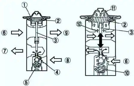
When the evaporator outlet refrigerant temperature decreases, PI + Fs becomes greater than Pd, the ball valve rises and the refrigerant flow decreases.
Capacitor
A condenser with additional cooling is used. This is a multi-flow condenser, which is equipped with an additional cooling element and is combined with a receiver/drier.
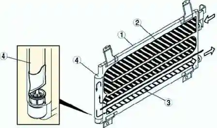
The aftercooled condenser separates the gaseous and liquid phases of the refrigerant initially cooled in the condenser in a receiver/dryer, where the refrigerant is returned to the aftercooler element and cooled again to accelerate liquefaction and improve cooling capacity.
Checking the heater core
Remove the air conditioning unit.
Remove the heater core of the air conditioning unit.
Check for cracks, damage, and coolant leaks.
If any problems are found, replace the heater core.
Check the plates for deformation.
Use a flat-tip screwdriver to eliminate deformation
Check that the heater core inlet and outlet pipes are not damaged. If necessary, eliminate the deformation with pliers.
Removing and installing the rear air duct
Turn the front floor covering over.
Remove the rear air duct (right side).
Remove the rear air duct (left side).
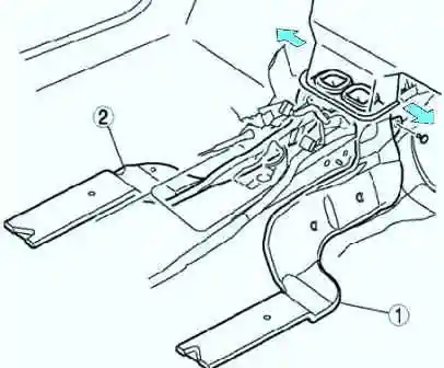
Install in the reverse order of removal.


