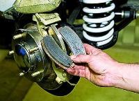
We remove the sensors of the engine management system for inspection or for replacement
Removing and installing the crankshaft position sensor
The sensor is installed on the cover of the gas distribution mechanism, in its lower part.
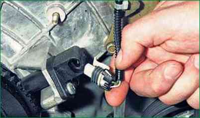
Press out the plastic latch securing the wiring harness block with a screwdriver or your finger and disconnect the block from the sensor.
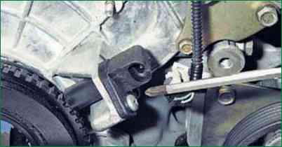
Remove the screw securing the sensor and remove the sensor from the hole of the cover tide
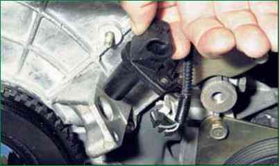
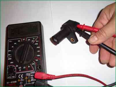
Check the resistance of the sensor. For a working sensor, it should be 0.55–0.75 kOhm.
Install the sensor in the reverse order of removal.
Removing and installing the coolant temperature sensor
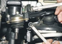
The sensor is screwed into the hole in the front pipe of the cylinder head water jacket.
You will need the key "for 19".
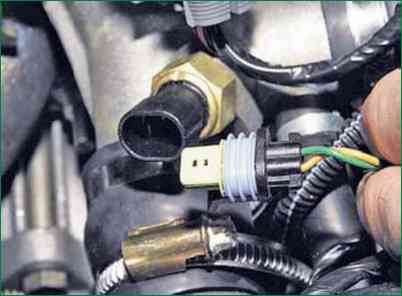
Press out the plastic latch securing the wiring harness block with a screwdriver or your finger and disconnect the block from the sensor.
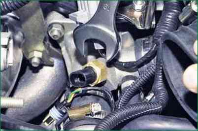
Loosen the sensor and unscrew it from the nozzle hole together with the O-ring.
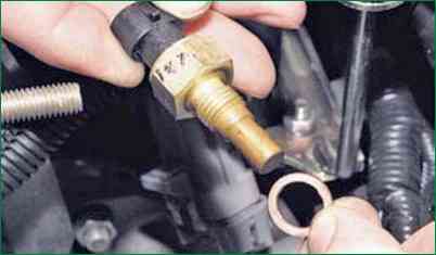
Check the resistance of the sensor. At 20°C, a good sensor should have a resistance of 2.2–2.4 kOhm.
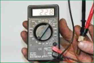
The resistance of the sensor varies with temperature over a wide range.
At high temperature, the sensor resistance is low (70 ohms at 130°C), and at low temperatures it is high (100.7 kOhm at -40°C).
Install the sensor in the reverse order of removal.
Removing and installing throttle position sensor
The sensor is mounted on the throttle assembly and connected to the throttle valve axis.
You will need a screwdriver.
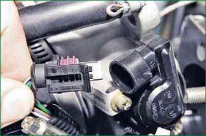
Disconnect the wiring harness from the sensor.
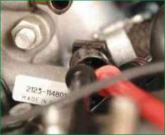
To check the health of the sensor, measure the resistance between terminals "2" and "3" of the sensor block.
Move the throttle from fully closed to fully open.
For a serviceable sensor, the resistance should change uniformly within 2.7–8.2 kOhm.
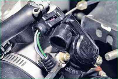
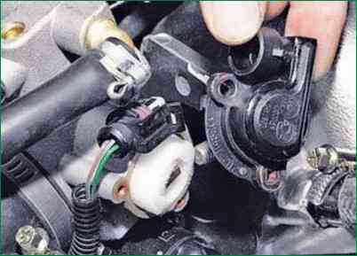
To replace a defective sensor, remove the two screws securing the throttle assembly and remove the sensor.
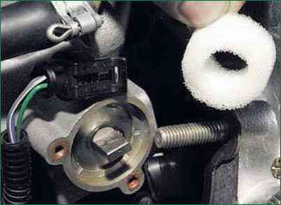
Please note: a sealing foam ring is installed under the sensor, do not forget to reinstall it.
Install the new sensor in the reverse order of removal.
Removing and installing the mass air flow sensor
The sensor is installed on the air filter outlet.
You will need: 10 wrench, screwdriver.
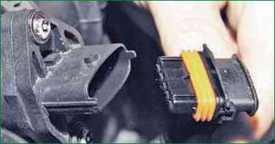
Disconnect the wiring harness from the sensor.
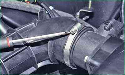
Loosen the clamp that secures the left side of the air supply pipe to the sensor and disconnect it from the sensor.
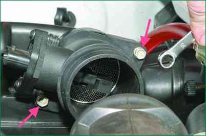
Remove the two bolts securing the sensor to the air filter cover and remove the sensor together with the O-ring
If the new sensor does not have a rubber o-ring, replace the O-ring from the removed sensor
Install the sensor in the reverse order of removal
Removing and installing knock sensor
The knock sensor is installed on the right side of the engine block in its upper part, in the region of the second and third cylinders.
You will need: 13 wrench, screwdriver.
The knock sensor is installed on the right side of the engine block in its upper part, in the region of the second and third cylinders.
For easier access to the sensor, unscrew the bolt of the lower mounting of the front intake pipe brace and move the brace to the side.
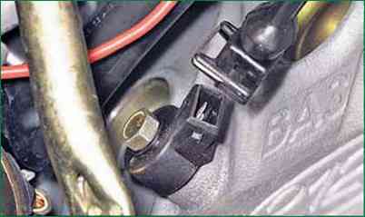
Press the spring clip of the wiring harness block and disconnect the block from the sensor
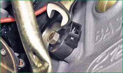
Remove the bolt securing the sensor to the cylinder block and remove the sensor.
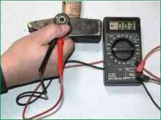
Connect an autotester connected in voltage measurement mode to the sensor terminals.
Tap the transducer body against a solid, massive object (such as a hammer).
In this case, the voltage should change.
If the voltage remains constant, the sensor is defective and needs to be replaced.
More accurately, the health of the sensor can be checked when the engine is running with the DST-2 diagnostic tool.
Install the sensor in the reverse order of removal.
Removing and installing the speed sensor
The sensor is installed on the rear cover of the transfer case, so it is more convenient to work on a lift or an inspection ditch.
You will need a "22" key.
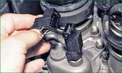
Pressing the spring clip, disconnect the wiring harness block from the sensor
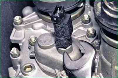
Loosen the sensor and unscrew it from the actuator.
Install the sensor in the reverse order of removal.
Removing the camshaft sensor (phase sensor)
This sensor is not installed on early production cars
If the sensor is faulty, the fault lamp in the instrument cluster lights up.
When idle for a long time, the engine does not start well.
Also weak engine response and increased fuel consumption.
The sensor is installed in front of the cylinder head.
To remove the sensor, disconnect the negative battery terminal
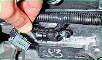
We press the latch and disconnect the block from the phase sensor
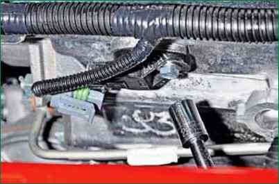
With a head of 10, unscrew the bolt securing the sensor to the cylinder head
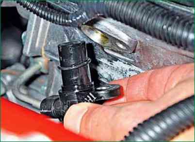
Remove the sensor from the hole in the block head
The sensor connection is sealed with a rubber ring (usually when buying a new sensor, it comes without this ring)
If the ring has lost its elasticity, it needs to be changed
Install the sensor in reverse order
The tightening torque of the sensor mounting bolt is 6-8 Nm.
Removing and installing oxygen concentration sensors
The replacement of sensors is provided for by the regulations after the car has been driven every 75 thousand km.
The control oxygen sensor is installed in the exhaust pipe, and the diagnostic sensor is installed between the catalytic converter and the additional silencer.
We replace sensors on a cold engine
Replacing the control sensor
Open the hood and disconnect the negative battery terminal
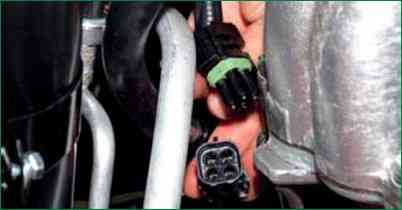
We press the block retainer and disconnect the sensor wire block from the CUD wire block
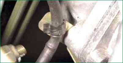
Disconnect the plastic holder of the sensor wiring harness from the bracket
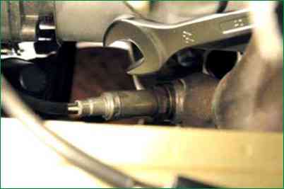
Unscrew the sensor with a 22 key
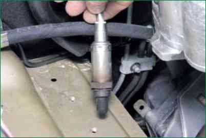
Remove the sensor from the engine compartment.
If the sensor cannot be unscrewed with an open-end wrench, then you will either have to disassemble the wire block or cut the wire going to the sensor (if the sensor needs to be replaced).
After that, you can put a ring wrench or head on the sensor and unscrew the sensor.
Replacing the diagnostic oxygen sensor
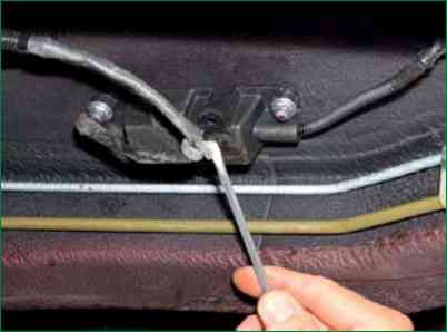
Pry from the bottom with a screwdriver and disconnect the plastic wire holder from the protective cover of the wire blocks.
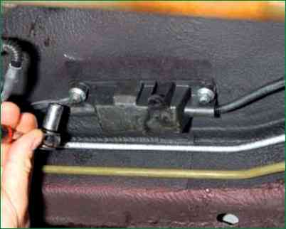
Use a 10 key to unscrew two nuts
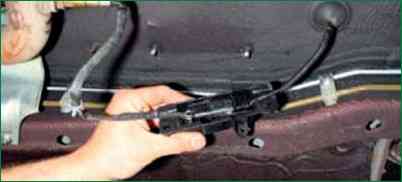
Remove the protective cover with wire blocks
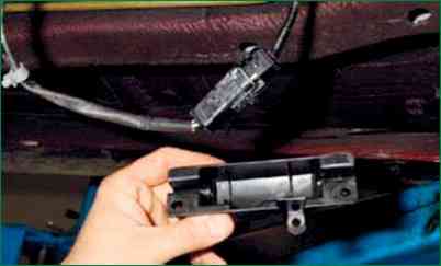
Remove the wire blocks from the protective cover
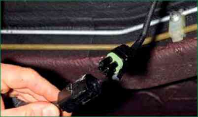
We press the pad retainer and disconnect the pads of the wiring harnesses
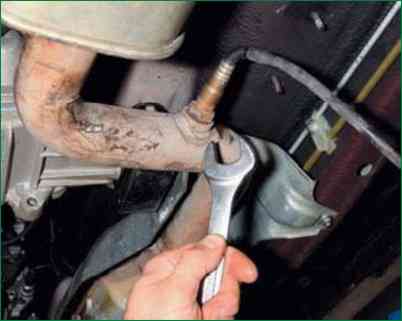
Use the 22 key to unscrew the diagnostic sensor
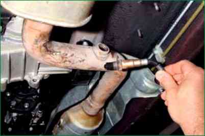
Remove the diagnostic sensor
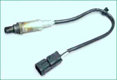
This is what an oxygen concentration sensor looks like
Install oxygen sensors in reverse order.
To prevent the sensors from sticking to the pipes, we lubricate the threaded part of the sensor with graphite grease.


