Engine lubrication system - combined: under pressure and splashing
Pressure oil lubricates the main and connecting rod bearings of the crankshaft, camshaft bearings, thrust bearings of the crankshaft and camshafts, rocker arm bushings and upper tips of the push rods.
The rest of the parts are lubricated with splashed oil.
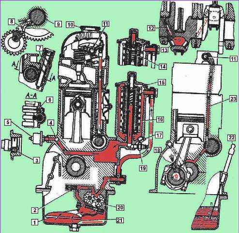
Scheme of the lubrication system: I - inlet pipe of the oil pump; 2 - pressure reducing valve; 3 - hole for draining oil; 4 - oil line; 5 - oil pressure indicator sensor; 6 - hole for supplying oil to the gears of the oil pump drive; 7 - helical groove; 8 - tube for lubrication of timing gears; 9 - groove on the first neck of the camshaft; 10 - oil filler cap; 11 - cavity in the axis of the valve levers; 12 - channel in the crankshaft; 13 - cork; 14 - bypass valve is open; 15 - bypass valve is closed; 16 - filter element; 17 - plug for draining sludge; 18 - hole for spraying oil; 19 - emergency oil pressure sensor; 20 - oil pump; 21 - cork; 22 - oil level indicator; 23 - channel for supplying oil to the axis of the valve levers
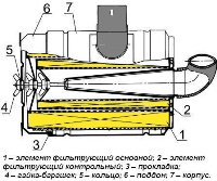
The lubrication system includes an oil pump 20 (Fig. 1) with a suction pipe and a pressure reducing valve (installed inside the oil sump), oil channels, an oil filter with a bypass valve, an oil sump, an oil level indicator, an oil filler cap, an indicator sensor oil pressure, emergency oil pressure alarm sensor.
The oil taken by the pump from the oil sump flows through the oil receiver through the channels in the pump housing and the outer tube into the oil filter housing.
Further, after passing through the filter element 16, the oil enters the cavity of the second partition of the cylinder block, from where along the drilled channel into the oil line - the longitudinal oil channel 4.
From the longitudinal channel, oil is supplied through inclined channels in the baffles of the block to the crankshaft main bearings and camshaft bearings.
Oil flowing from the fifth bearing of the camshaft into the cavity of the block between the shaft and the plug is discharged into the crankcase through the transverse hole 3 in the shaft neck.
The crankpins are supplied with oil through channels 12 from the main journals of the crankshaft.
Oil is supplied to the rocker arm axle from the rear camshaft bearing, which has an annular groove in the middle, which communicates through channels 23 in the block, cylinder head and in the fourth main rack of the rocker arm axle with cavity 11 in the rocker arm axle.
Through the holes in the axis of the rocker arms, oil enters the bushings of the rocker arms and then through the channels in the rocker arms and adjusting screws to the upper tips of the pusher rods.
Oil is supplied to the gears of the camshaft drive through a tube 8, pressed into a hole in the front end of the block, connected to an annular groove 9 on the first camshaft journal.
A jet of oil is ejected from the outlet of the tube, which has a small diameter, directed at the gear teeth.
Through a transverse channel in the first camshaft journal, oil from the same journal groove also enters the camshaft thrust flange.
The oil pump drive gears are lubricated by a jet of oil ejected from channel 6 in the block connected to the fourth camshaft journal, which also has an annular groove.
The walls of the cylinders are lubricated by oil splashes from the jet ejected from hole 18 in the lower connecting rod head when this hole coincides with the channel in the crankshaft journal, as well as by oil flowing from under the crankshaft bearings.
All other parts (valve - its stem and end, oil pump drive shaft and ignition distribution sensor, camshaft cams) are lubricated with oil flowing from the gaps in the bearings and sprayed by moving engine parts.
The capacity of the lubrication system is 6 liters
Oil is poured into the engine through the oil filler neck located on the cover of the rocker arms and closed with a cover with a sealing rubber gasket.
The oil level is controlled by the "P" and "O" marks on the level indicator rod.
The oil level should be maintained between the "P" and "O" marks.
The pressure in the lubrication system at average vehicle speeds (approximately 50 km/h) should be 200–400 kPa (2–4 kgf/cm 2).
It can rise to 450 kPa (4.5 kgf/cm 2) on a cold engine and drop to 150 kPa (1.5 kgf/cm 2) in hot weather >).
A decrease in oil pressure at an average speed below 100 kPa (1 kgf / cm 2) and at a low idle speed - below 50 kPa (0.5 kgf / cm 2) indicates a malfunction in the lubrication system or excessive wear of the crankshaft and camshaft bearings.
Further operation of the engine under these conditions should be stopped.
Oil pressure is determined by a gauge on the instrument panel, the gauge of which is screwed into the oil filter housing.
In addition, the system is equipped with an alarm lamp for emergency oil pressure, the sensor of which is screwed into the hole in the bottom of the filter.
The signal lamp is located on the instrument panel and glows red when the pressure in the system drops below 40-80 kPa (0.4-0.8 kgf / cm 2).
You must not operate a vehicle with a glowing emergency oil pressure lamp.
Only a short glow of the lamp is allowed at low idling speed and when braking.
If the system is working, then with a slight increase in the speed of rotation, the lamp goes out.
In case of underestimation or overestimation of oil pressure from the above values, you should first check the serviceability of sensors and indicators.


