")
")
")
")
")
")
Hydraulic pushers of the VAZ-21126 engine, made in the form of cylindrical pushers located between the camshaft and valves, combine two functions:
- transferring force from the camshaft to the valves and eliminating gaps in their drive.
The operation of the hydraulic pusher is based on the principle of incompressibility of engine oil, which constantly fills the internal cavity of the hydraulic pusher during engine operation and moves its plunger when a gap appears in the valve drive.
Thus, constant contact of the pusher with the camshaft cam without play is ensured.
This eliminates the need for valve adjustment during maintenance.
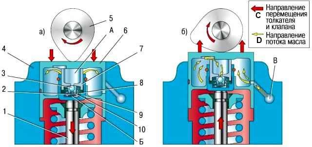
Oil under pressure necessary for the operation of the hydraulic pusher is supplied to the internal cavities (A) and (B) from the channel (C) of the engine lubrication system through the side hole in the pusher 6, made in the annular groove of its cylindrical surface.
When the valve 1 is closed, the pusher 6 (through the plunger 7) and the sleeve 9 are pressed by the expanding force of the spring 8, respectively, to the cam 5 of the camshaft and the end of the valve stem.
The pressure in the cavities (A) and (B) is the same, the check valve 3 of the hydraulic pusher is pressed against the seat in the plunger 7 by the spring 2 - there are no gaps in the valve mechanism.
When the camshaft rotates, the cam 5 runs into the pusher 6, moving it and the associated plunger 7.
Moving the plunger 7 in the sleeve 9 leads to a sharp increase in pressure in the cavity (B).
Despite small oil leaks through the gap between the plunger and the sleeve, the pusher 6 and sleeve 9 move in one piece and open valve 1.
With further rotation of the camshaft, cam 5 reduces the pressure on the pusher 6 and the oil pressure in cavity (B) becomes lower than in cavity (A).
Return valve 3 opens and passes oil from the cavity (A), connected to the engine oil line, into the cavity (B).
The pressure in the cavity (B) increases, the sleeve 9 and the plunger 7, moving relative to each other, select the gap in the valve mechanism.
The pressure of the oil supplied to the hydraulic pushers is regulated by a valve installed in the cylinder head.
Since after the engine is stopped, oil drains from the channels coming from the oil pump into the oil sump, and the channels for supplying oil to the hydraulic pushers remain filled, air locks may form in the cavities of the latter after the engine is started.
To eliminate them, calibration compensatory holes are provided in the engine oil supply channels, which provide automatic purge of the cavities of the hydraulic pushers.
In addition, compensation holes allow you to somewhat reduce the pressure of the oil entering the hydraulic pushers at a high engine speed, when the pressure in the hydraulic pusher cavity can become so high that its pusher, leaning on the back of the camshaft cam, slightly opens the valve at the moment , which does not correspond to the valve timing.
Almost all malfunctions of hydraulic pushers are diagnosed by the characteristic noise emitted by the gas distribution mechanism in various engine operating modes.
Noise from valves can sometimes be eliminated by slightly turning the spring or valve around the longitudinal axis. To do this, do the following.
- 1. Rotate the crankshaft until the valve making the noise starts to open slightly.
- 2. Turn the spring a little and the valve will turn at the same time.
- 3. Start the engine. If the noise persists, repeat steps 1 and 2.
- 4. If turning the spring and the valve does not give the desired result, check the condition of the spring and measure the clearances between the valve stems and guide bushings. Eliminate increased (compared to nominal) clearances.
If the valve and spring are in good condition, and the knock of the valves is still heard when the engine is running, the hydraulic pusher is faulty. Replace it with the following.
Perform work 20–30 minutes after stopping the engine.
Remove the cylinder head cover (see Replacing the cylinder head cover gasket VAZ-21126).
Remove the camshafts.

To check the hydraulic pusher, press it.
If the hydraulic pusher is in good condition, it should sink in with considerable force, if this force is small, the hydraulic pusher is faulty.
It is also necessary to check the ease of rotation of the hydraulic pusher in the socket of the block head.
If the hydraulic tappet does not rotate or rotates with great effort, it must be replaced.

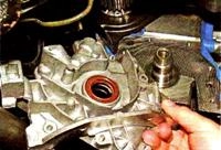
Remove the hydraulic tappet from the cylinder head seat. Remove the hydraulic pusher with a conveniently sized magnet.

Lubricate the hydraulic tappet and seat in the cylinder head with engine oil and install the hydraulic tappet in the seat
The rest of the hydraulic pushers are replaced similarly.7. Install the camshaft and timing drive parts in the reverse order of removal
After replacing the hydraulic pusher, the engine may run with increased noise for a short time at the first start until the hydraulic pushers are pumped.
To speed up the pumping of the hydraulic pushers, let the engine run at an increased speed for 1–2 minutes.
Possible malfunctions of hydraulic pushers, their causes and solutions
- Cause of malfunction Remedy
Increased noise immediately after starting the engine:
Oil leakage from part of the hydraulic pushers during a long stop.
The noise that disappears a few seconds after starting the engine is not a sign of a malfunction, since oil leaked out from a part of the hydraulic pushers that were under the load of the valve springs of the open valves (the oil supply channels remained open), the lack of which is replenished at the start of the engine operation
Intermittent idle noise that disappears as engine speed increases:
- Damage or wear of the check valve ball
Replace hydraulic tappet
- Pollution of the hydraulic pusher mechanism with wear products due to untimely oil changes or its low quality
Clean the parts of the mechanism from dirt. Use the oil recommended in the owner's manual
Increased noise during idling of a warm engine, disappearing at an increased crankshaft speed and completely absent on a cold engine:
- Oil flow through the gaps increased due to wear between the plunger and the hydraulic pusher sleeve
Replace worn hydraulic tappet assembly
Increased noise that occurs at high crankshaft speed and disappears at low speed:
- Foaming with excess oil (above the upper mark on the dipstick) in the oil sump due to its agitation by the crankshaft.
The ingress of an air-foamy oil mixture into the hydraulic pushers disrupts their operation
Top up the oil level in the oil sump
- Air intake by the oil pump when the oil level in the oil sump is too low
Top up the oil level in the oil sump
- Damage to the oil receiver due to deformation of the oil sump when hitting a road obstacle
Repair or replace defective parts
Constant noise from one or more valves, independent of engine speed:
- The occurrence of a gap between the pusher and the camshaft cam due to damage or contamination of the parts of the hydraulic pusher
Remove the cylinder head cover, install the camshaft cams alternately with the projections up and check for a gap between the pushers and the cams.
Sinking (for example, with a wooden wedge) the hydraulic pusher to be checked, compare the speed of its movement with the others.
If there is a gap or an increased travel speed, disassemble the hydraulic pusher and clean its parts from dirt or replace the hydraulic pusher
*The following reasons for increased noise in idle mode are possible, which increases with increasing crankshaft speed up to 1500 min -1 and is not associated with the operation of hydraulic pushers:
- - increased clearances between valve stems and guide bushings;
- - valve and seat misalignment increased to a value exceeding the allowable value;
- - non-parallelism of the ends of the valve springs;
- – greater than the allowable runout of the chamfer of the valve head.
*The following reasons for increased noise in idle mode are possible, which increases with increasing crankshaft speed up to 1500 min -1 and is not associated with the operation of hydraulic pushers:
- - increased gaps between valve stems and guide bushings;
- - valve and seat misalignment increased to a value exceeding the allowable value;
- - non-parallelism of the ends of the valve springs;
- - more than allowable runout of the valve head chamfer.