")
")
")
")
")
")
Dismantling a pair of injection gears, as well as the housing and cover of the oil pump is not allowed
There must be no cracks on the pump body and cover, as well as damage or stripped threads
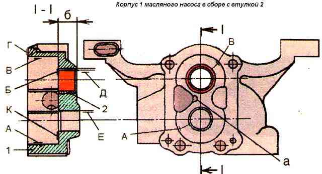
The non-flatness of the surface "G" (Fig. 1) of the pump casing should not exceed 0.03 mm over the entire length.
The amount of local wear of the surface "B" of the oil pump housing in places mating with the injection gears is allowed up to 0.03 mm.
With a greater amount of wear, grinding of the body is allowed; while the roughness of the treated surface should be Ra≤1.25 µm.
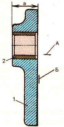
The thickness of the cover (dimension "a" in Fig. 2) is allowed at least 16 mm.
The non-flatness of the surface "B" of the pump cover should not exceed 0.03 mm.
The non-perpendicularity of the surface "B" to the surface "A" should not exceed 0.03 mm over the entire length.
The height of the injection gears must be the same and equal to 28-0.040 mm; height difference is allowed no more than 0.03 mm.
The depth of the pump housing pockets for the pressure gears must be the same with a tolerance of 0.06 mm.
If the difference in the depths of the sockets is more than 0.06 mm or if there are deep scratches and scuffs on the end surfaces of the sockets, processing is allowed until the wear marks are removed.
The runout of the machined surface "B" (see Fig. 1) relative to the surface "D" of the surface "K" relative to the surface "D", surface "K", relative to the surface "E" at a radius of 18 mm should not exceed 0, 05 mm.
It is allowed to deepen the nests by an amount at which the dimension "b" will be at least 15 mm.
The roughness of the treated surfaces is Ra≤0.25 µm. Beat control according to RTM 70.0001.234-83.
The depth of the groove (dimension "a") on the pump housing must be at least 3 mm.
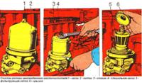
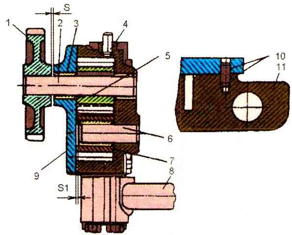
The sinking of the end of the pin of the driven gear relative to the plane of the connector of the pump housing (S1) should be within 0.7-1.3 mm (Fig. 3).
The protrusion of the bushing over the ends of the driven gear of the pump and the surfaces of the pump cover is not allowed.
The out-of-roundness and tolerance of the profile of the longitudinal section of the hole of the bushing of the driven gear, after processing, should not exceed 0.025 mm.
The sinking of the injection gears of the oil pump relative to the surface "G" (see Fig. 1) should be within 0.04-0.13 mm.
At a higher sinking value, it is allowed to remove metal from the “G” surface.
The runout of the machined surface "P" relative to the surface D at a radius of 29 mm should not exceed 0.07 mm.
The roughness of the machined surface should be Ra ≤ 1.25 µm.
The diameter of the holes in the bushings of the pump housing and cover, as well as the bushing of the driven gear must correspond to 1 8 + 0.059 mm. With a larger diameter, replace the bushings with new ones, followed by processing to the required diameter.
The bushing must be pressed into the oil pump housing flush with surface "B".
Machining the holes of the sleeves must be carried out on the assembled pump housing with a cover with one installation of the tool. Surface roughness Ra ≤ 2.25 µm.
The out-of-roundness and tolerance of the profile of the longitudinal section of the machined holes is 0.025 mm.
The diameter of the pump housing sockets in the areas of greatest wear should be 42.25 mm.
When surfaces “A” and “B” are worn to a diameter of more than 42.41 mm, it is allowed to restore them with subsequent boring to the diameter of a new body.
Eccentric boring of nests for gears of nominal size is also allowed with displacement of the axes of the nests towards the suction channel of the pump. Offset is allowed up to 2.1 mm.
The roughness of the machined surfaces is Ra ≤ 0.20 µm.
The radial clearance between the pump housing and the tops of the teeth of the pumping gears should be within 0.125-0.245 mm.
The gaps between the holes of the housing bushings, the pump covers and the pump shaft, as well as between the bushing hole and the axis of the driven gear should be within 0.032-0.07 mm.
The protrusion of cylindrical pins 4 (see Fig. 3) above the mating plane should be 7 ± 0.2 mm.
The gap S between the end face of the drive gear hub and the cover on the assembled pump should be no more than 0.2
The bolts securing the pump cover to the housing must be tightened to a torque of 18-25 Nm.
The gears of the assembled pump should turn freely by hand, without jamming and jerking.
The run-in and testing of the oil pump on the ki-5278 bench should be carried out on a mixture of engine oil and diesel fuel having a viscosity of 11.5-16 mm 2/s (cSt) at the test temperature.
The use of other mineral oils is allowed, provided that the specified viscosity is maintained during the test.
At a test temperature of 18-22°C, a mixture consisting of 40% M-10G engine oil and 60% diesel fuel can be used.
The oil pump must be run in at a pump shaft speed of 2320±50 min -1 every time for 2 min at a pump outlet pressure of 0.30±02 MPa and a back pressure of 0.7± 0.3 MPa.
During the running-in process, overheating of parts, extraneous noise, as well as oil leakage at the junction points are not allowed. Slight oil leakage is allowed through the gaps between the pump shaft, the bushings of the housing and the pump cover.
The assembled pump must be tested on the bench. At a pump shaft speed of 3170 ± 25 min -1, a back pressure at the pump outlet of 0.7-0.75 MPa, the volume flow of the repaired pump should be at least 0.8 dm 3 >/s, and the power spent on the drive is not more than 1.3 kW.
When testing nozzles for tightness with diesel fuel or air at a pressure of 0.1 ± 0.02 MPa, no leaks, drops or air infiltration are allowed.
The non-flatness of the mating planes of the connecting flanges of the outlet pipe should not exceed 0.05 mm.
When testing the outlet pipe for tightness with water at a pressure of 1.0 MPa, no leaks or drops of water are allowed.