")
")
")
")
")
")
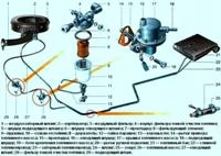
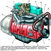
Oil pump (Fig. 1.) gear type installed inside the oil sump
The pump is attached with two studs to the ramps on the third and fourth baffles of the cylinder block
The accuracy of the pump installation is ensured by two bushing pins pressed into the cylinder block.
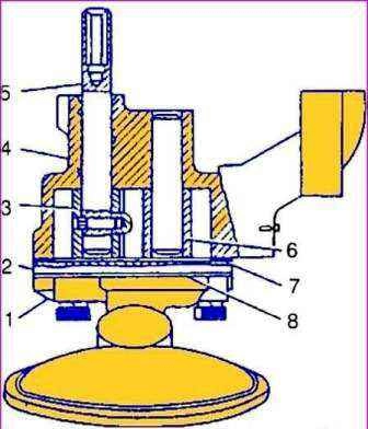
Pump housing 4 is cast from aluminum alloy, gears 3 and 6 have straight teeth and are made of cermet (sintered metal powder).
Drive gear 3 is fixed on shaft 5 with a pin.
A hexagonal hole is made at the upper end of the roller, into which the oil pump drive shaft enters.
Driven gear 6 rotates freely on an axle pressed into the pump housing.
The cover 2 of the pump is made of gray cast iron and is attached to the pump with four bolts. A 0.3 mm thick cardboard gasket is placed under the lid.
The oil receiver and the intake pipe of 1 oil pump are made in a single housing made of aluminum alloy.
A mesh is rolled on the receiving part of the nozzle.
The branch pipe is attached to the oil pump with four bolts together with the oil pump cover through the paronite gasket 8.
The performance of the oil pump is much higher than required by the engine.
The performance margin is necessary to ensure the appropriate oil pressure in the system at any engine operating mode.
At the same time, excess oil flows from the discharge cavity of the pump through the pressure reducing valve back into the suction cavity.
With an increase in oil consumption through the gaps in the bearings (if the engine wears out), the required pressure is also maintained in the system, but in this case, a smaller amount of oil passes through the pressure reducing valve back into the pump intake cavity.
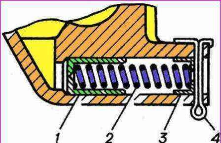
The plunger-type pressure reducing valve is located in the oil pump housing.
The end of plunger 1 (Fig. 2.) is affected by oil pressure, under the influence of which the plunger, overcoming the force of spring 2, moves.
When a certain pressure is reached, the plunger opens the drain channel opening, passing excess oil into the pump intake cavity.
The pressure reducing valve spring rests on a flat washer 3 and is fastened with a cotter pin 4, passed through the holes in the lug on the pump housing.
Reducing valve is not adjustable; the required pressure characteristic is provided by the geometric dimensions of the pump housing and the characteristic of the spring: to compress the spring to a length of 40 mm, a force of 43.5–48.5 N (4.35–4.85 kgf) is required.
In operation, it is not allowed to change the spring force of the pressure reducing valve in any way.
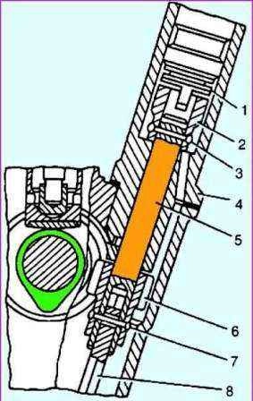
The drive of the oil pump and the ignition distribution sensor (Fig. 3.) is carried out from the camshaft by a pair of helical gears.
The drive gear is steel, cast into the body of the cast-iron camshaft.
Driven gear 8 is made of steel, heat-strengthened, fixed with a pin on roller 5, rotating in a cast-iron housing.
The upper end of the roller is equipped with a sleeve 2, which has a slot (displaced by 1.15 mm from the axis of the roller) for driving the ignition distributor sensor.
The sleeve on the roller is secured with pin 3.
A hexagonal roller 10 is pivotally connected to the lower end of the roller, the lower end of which enters the hexagonal hole of the oil pump roller.
During rotation, gear 8 is pressed against the end of the cast-iron drive housing through thrust washers 6 and 7.
This assembly, as well as the roller in the drive housing, is lubricated with oil sprayed by the drive gears and flowing down the block wall.
The oil flowing down the walls enters the slot (trap) on the lower end of the drive housing and then through the hole onto the surface of the roller.
A spiral groove is cut into the hole for the roller in the drive housing, along which the oil rotates when the roller rises up and is evenly distributed along its entire length.
Excess oil from the upper cavity of the drive housing is drained back to the crankcase through the drain hole in the housing.
The correct position of the ignition distributor on the engine is ensured by such an installation of the drive in the block, in which at the moment the piston of the first cylinder is at TDC (compression stroke), the slot on the drive sleeve is parallel to the engine axis at the maximum distance from it.
Repair and replacement of the ZMZ-402 oil pump
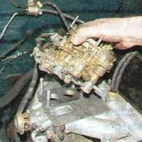
We remove the oil pump if the oil pressure does not correspond to the norm and during the overhaul of the engine.
To remove the oil pump, you need to remove the oil pan, as described in the article - ZMZ-402 engine disassembly sequence 402.

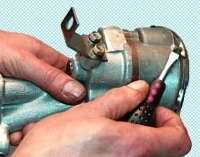
With a 13 head, unscrew the two nuts securing the oil pump
Remove the oil pump

If the oil pump was removed due to a defect - (the oil pressure is not up to standard), then you should immediately pay attention to the grid of the oil pump intake.
It happens that the oil receiver mesh is very clogged and therefore the oil pressure is low.
To flush the oil pump, you can dip the assembly into a container of gasoline, and rotate the drive gear to flush the pump.
Oil pump disassembly

Using a 12 key, we unscrew the four screws securing the oil receiver

Remove the oil receiver of the oil pump.

Remove the cover

Removing the drive gear

Take out the driven gear

We unpin the fastening of the pressure reducing valve and remove its parts.
Oil pump inspection and check
If there is wear on the partition (cover for mod. 402), it must be sanded so that no traces of wear remain.
Inspect the hull. If it is badly worn, you need to replace the pump.
The gears in the pump housing must turn completely freely.
The pressure relief valve plunger must move completely freely in the body.
Inspect the relief valve spring. If cracks are visible on it or the coils are broken, replace the spring.
The length and stiffness of the spring are selected at the factory in such a way that the operation of the pressure reducing valve is optimal, therefore, the length and stiffness of the spring must not be changed in any way.
For the ZMZ-402 engine, in order to compress the spring to a length of 40 mm, it is necessary to apply a force of 43.5–48.5 N (4.35–4.85 kgf).
If the spring does not meet at least one of these requirements, it must be replaced.

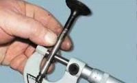
The gap between the ends of the gears and the plane of the housing should be 0.040-0.140 mm.

When measuring with a flat feeler gauge, the clearance between the outer diameter of the gears and the housing should be 0.120-0.215 mm.

The gap between the gear teeth should be no more than 0.15 mm.
If these values do not match, then you need to replace the pump parts or replace the pump.
Pump assembly
We assemble the oil pump in the reverse order, lubricating the rubbing parts with engine oil.
When assembling the motor pump mod. 402 under the pump cover, you need to put a cardboard gasket 0.3 mm thick.
It is forbidden to install a gasket of a different thickness or use sealant, paint, etc. when installing the gasket, as this will reduce the performance of the pump.
Install the pump in reverse order.
We tighten the oil pump mounting nuts with a torque of 18-25 Nm (1.8-2.5 kgf.m).