")
")
")
")
")
")
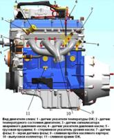
The VAZ-21126 engine, based on the VAZ-2112 engine, is installed on the VAZ-2170 Lada Priora car
Increased engine displacement mod. 21126 up to 1.6 l compared to the displacement mod. 2112 is achieved by increasing the piston stroke with the same cylinder diameter.
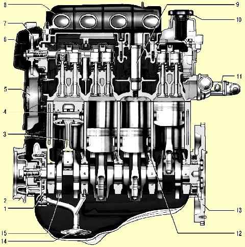
The cylinder block is cast from special high-strength cast iron, which gives the engine rigidity and strength.
The channels for the coolant forming the cooling jacket are made along the entire height of the block, this improves the cooling of the pistons and reduces the deformation of the block from uneven overheating.
The cooling jacket is open at the top towards the block head. At the bottom of the cylinder block are five crankshaft main bearings, the covers of which are bolted.
The supports are equipped with thin-walled steel-aluminum liners that act as crankshaft bearings.
In the middle support, grooves are made, into which thrust half rings are inserted, holding the crankshaft from axial movement.
Compared to the engine block mod. 2112 cylinder block mod. 21126 is 2.3 mm higher, the height from the axis of the main bearing beds to the upper surface of the block is 197.1 mm.
Crankshaft is cast from special ductile iron. The main and connecting rod journals of the shaft are ground.
To lubricate the connecting rod bearings, oil channels closed with plugs are drilled in the crankshaft.
There are eight counterweights located on the crankshaft to reduce vibration.
Crank radius mod. 21126 is 2.3 mm larger than the motor mod. 2112, due to which the piston stroke increased from 71 to 75.6 mm.
To distinguish the shafts on one of the counterweights of the crankshaft of the VAZ-21126 engine, the marking "11183" is cast.
At the front end of the crankshaft there is an oil pump, a toothed pulley for the camshaft drive belt and an alternator drive pulley with an integrated vibration damper.
At the rear end of the crankshaft is a cast iron flywheel. A steel toothed rim is pressed onto the flywheel.
Steel forged connecting rods with caps on lower heads. The connecting rod caps are made by tearing off a solid connecting rod.
This achieves a higher accuracy of fitting the cap on the connecting rod. Thin-walled liners are installed in the lower head of the connecting rod, and a steel-bronze bushing is pressed into the upper head.
Pistons cast from aluminum alloy. Each of them has three rings: two upper compression rings and a lower oil scraper.
The bottom of the pistons is flat, with four recesses for valves, and on the pistons of the engine mod. 21126 the recesses are larger than those of the 2112 engine.
Pistons are cooled by oil, for which special nozzles are installed in the main bearing supports. They are tubes containing spring-loaded balls.
During engine operation, the balls open holes in the tubes, and a jet of oil hits the piston from below.
In the engine mod. 21126, the piston-piston rings-piston pin-connecting rod set of reduced weight was used (the weight of the piston was reduced from 350 to 235 g, the piston pin from 113 to 65 g, the connecting rod from 707 to 485 g, the entire set by 32%) .
Steel oil sump, stamped, bolted to the cylinder block from below.
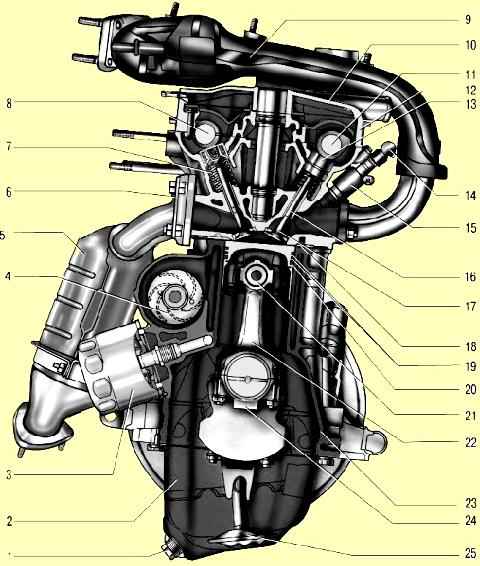
The head of the block, mounted on top of the cylinder block, is cast from an aluminum alloy.
At the bottom of the head, channels are cast through which the liquid circulates, which cools the combustion chambers.
At the top of the head are two camshafts: one for the intake valves, the other for the exhaust.
Cylinder head mod. 21126 differs from head mod. 2112 with an increased area of the flanges for the inlet pipeline and the glasses of candle wells made in one piece with the head of the block.
The camshafts are mounted in bearings made in the upper part of the block head and in one common bearing housing bolted to the block head.
Camshafts are cast iron.
The camshaft pulleys of the 21126 engine differ from the pulleys of the 2112 engine by shifting the timing marks by 2 °.
To reduce wear, the working surfaces of the cams and the surfaces under the stuffing box are heat-treated - bleached.
Camshaft lobes actuate valves through tappets.
The 21126 engine is equipped with valve lifters that automatically compensate for valve clearances.
This engine does not need to adjust valve clearances during operation.
The engine has four valves per cylinder: two intake and two exhaust.
Guides and valve seats are pressed into the block head.
The guide bushings are also equipped with retaining rings to keep them from falling out.
The guide bushings are fitted with oil scraper caps, which reduce the ingress of oil into the cylinders.
One spring is installed on each valve.
The camshafts are driven by a rubber toothed belt from the crankshaft.
The cylinder head cover is made of aluminum.
The junction of the cover with the cylinder head is sealed with a gasket.
The cylinder head cover of the 21126 engine differs from the cover of the 2112 in the absence of a platform for attaching the ignition module and the presence of holes for attaching individual ignition coils next to the candle wells.
Engine lubrication system combined: spray and pressure.
Main and connecting rod bearings, camshaft bearings are lubricated under pressure.
The system consists of an oil sump, a gear oil pump with an oil receiver, a full-flow oil filter, an oil pressure sensor and oil channels.
The engine cooling system consists of a cooling jacket, a radiator with an electric fan, a centrifugal water pump, a thermostat, an expansion tank and hoses.
The power supply system includes an electric fuel pump installed in the fuel tank, a throttle assembly, a fine fuel filter, a fuel pressure regulator, injectors, fuel hoses.
Differences in the elements of the power supply system of the engine mod. 21126 from engine mod. 2112:
- - tubular fuel rail without fuel backflow is made of stainless steel instead of aluminum alloy;
- - fuel injectors of reduced size are not interchangeable with the previous ones;
- - Redesigned fuel pressure regulator installed in the fuel pump module instead of on the fuel rail;
- - there is no hole in the throttle assembly connecting the air supply hose to the intake module, bypassing the throttle valve.
The configuration of the throttle assembly flange has been changed. The fuel system functionally includes a fuel vapor recovery system with a carbon adsorber, which prevents fuel vapors from escaping into the atmosphere.
The ignition system consists of individual ignition coils mounted on the cylinder head cover and spark plugs.
The electronic control unit (ECU) of the engine controls the ignition coils.
Installation of individual ignition coils instead of the engine ignition module mod. 2112 made it possible to abandon high-voltage ignition wires and improve the performance and reliability of the system.
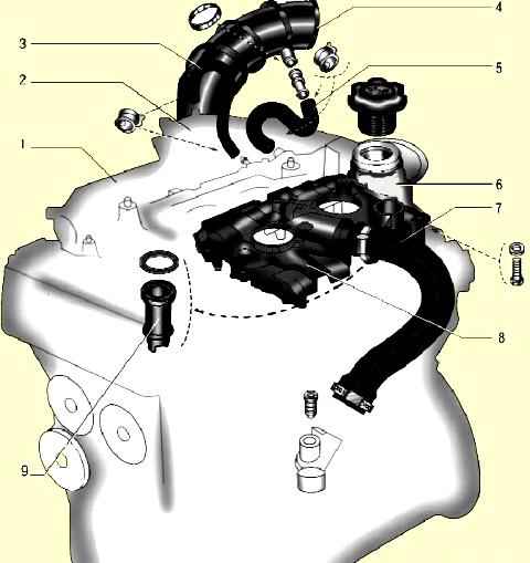
Crankcase ventilation system closed, with crankcase gases vented through separator 8 (Fig. 3) of the oil separator installed in the cover 6 of the cylinder head, into the intake truba.
Further crankcase gases are sent to the engine cylinders, where they are burned.
When the engine is idling, crankcase gases enter through hose 3 of the small circuit through a calibrated hole (jet) in the throttle body.
In this mode, a high vacuum is created in the intake pipe and crankcase gases are effectively sucked into the throttle space.
The jet limits the amount of exhaust gases so that the engine does not interfere with idling.
When the engine is running under load, when the throttle is partially or fully open, the main volume of gases passes through hose 5 of the large circuit into the air supply hose 4 in front of the throttle assembly and then into the intake manifold and combustion chambers.