")
")
")
")
")
")
- 1. Remove the cylinder head.
- 2. Remove the oil pump.
- 3. Loosen the nuts 1 of the connecting rod bolts and remove the connecting rod cap 2.

Since the lid sits tightly, knock it down with gentle hammer blows.
Remove the connecting rod bearing shell from the cover.
- 4. Push the piston into the cylinder so that it comes out of the cylinder, and then remove it along with the connecting rod.
Remove the connecting rod bearing shell from the lower end of the connecting rod.
Remove the piston with the connecting rod from the cylinder carefully so as not to damage the cylinder mirror.
Check the marks on the connecting rod and connecting rod cap.
If the marks are not visible, mark the connecting rod and cap with the cylinder number.
- 5. In the same way, remove the remaining pistons with connecting rods.
- 6. Using a puller, remove the piston rings.

- 7. Remove the circlips from both sides of the piston.
- 8. Press out the piston pins with a special tool.
If there is no tool, you can knock out the piston pins with light hammer blows through the mandrel 1 - this must be done by weight so as not to damage the piston.

Remove connecting rod 2 from piston 3.
- 9. In the same way, remove the remaining pistons from the connecting rods.
- 10. After disassembly, wash all parts in gasoline.
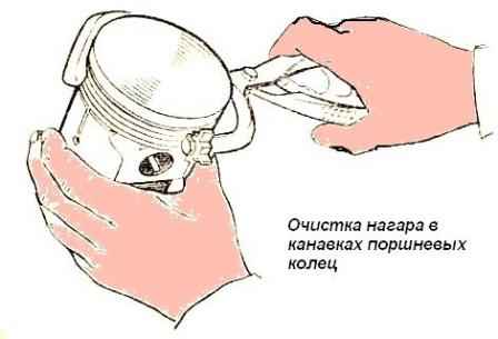
Clean the piston crowns and piston ring grooves from carbon deposits as shown in fig. 6;
- - in case of replacing a piston, piston pin or connecting rod, you must:
- - remove the piston pin retaining rings with pliers;
- - remove the piston pin on the tool (piston rings must be removed before this);
- - pick up new pistons according to the sleeves with a gap of 0.012-0.024 mm.
Selection is checked by pulling a probe tape between the piston and cylinder using a spring steelyard.
The probe is located in a plane perpendicular to the axis of the piston pin.
The piston must be without piston rings.
The pulling force at normal room temperature (+20°C) should be in the range of 3.5-4.5 kg.
Tape dimensions: thickness -0.05 mm, width - 13 mm, length - 250 mm;
- - pick up the piston pin to the connecting rod so that at normal room temperature it moves smoothly in the hole of the upper head under a slight effort of the thumb.
Piston pin, should be lightly oiled.
The color of the pin marking must match the color of the marking on the piston bosses;
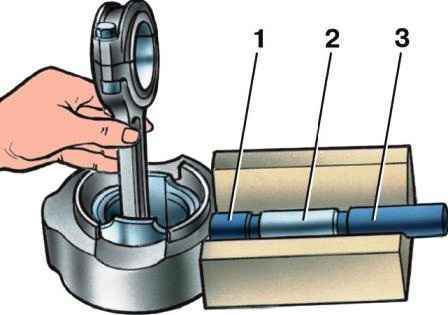
- - make a subassembly of the connecting rod and piston group on the fixture (Fig. 7).
Before pressing the piston pin into it, the piston must be heated in hot water to a temperature of 70 ° C; pressing a finger against a cold piston can damage the surface of the holes in the piston bosses, as well as deformation of the piston itself.
Insert the circlips of the piston pin into the annular grooves of the piston bosses;
- - select piston rings according to the cylinder; gap; measured at the joint of the ring with a feeler gauge, should be 0.3 - 0.5 mm.
In worn cylinders, the smallest clearance should be 0.3 mm;
- - use a feeler gauge to check the side clearance between the ring and the wall of the piston groove (Fig. 8).

Check along the circumference of the piston at several points.
The value of the side clearance for the upper compression ring should be within 0.050-0.082 mm, and for the lower compression and oil scraper rings - 0.035 - 0.067 mm;
- - put the piston rings on the piston using the tool.
Compression rings are placed with the internal chamfer to the piston crown, as shown in fig. 12, the rings in the grooves should move freely;
- - wipe the beds of the connecting rods and their caps with a napkin, wipe and insert the liners into them;
- - turn the crankshaft so that the cranks of the first and fourth cylinders take the position corresponding to the bottom dead center;
- - lubricate the liners, piston, connecting rod neck of the shaft and the sleeve of the first cylinder with clean engine oil, spread the joints of the piston rings at an angle of 120 ° to each other, put protective brass tips on the connecting rod bolts, compress the rings by crimping or using a cone ring ( Fig. 9), insert the piston into the cylinder.
Before installing the piston, you should once again make sure that the numbers stamped on the connecting rod and its cover correspond to the serial number of the cylinder, check the correct position of the piston and connecting rod in the cylinder; the mark on the piston “Back” should be directed towards the flywheel, and the hole in the lower head of the connecting rod should be in the direction opposite to the camshaft;
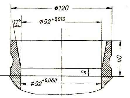
Dimensional groups of pistons, connecting rods and pins

Nominal and maximum allowable dimensions, fit of mating parts of the connecting rod and piston group of the engine mod. 402