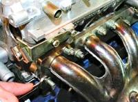
Check whether the size group of the piston set matches the size group of the cylinder liners
Pistons of one set on a diesel engine must be of the same size group corresponding to the size group of cylinder liners.
The difference in the mass of pistons of one set should not exceed 10 g.
The mass difference between connecting rods and pistons must not exceed 30 g.
Check that the size group of the connecting rod bearings matches the repair or nominal size of the connecting rod journals.
Size groups of pistons and cylinder liners are shown in the table.
Before installing the piston assembly with connecting rods and piston rings in the liners, wipe with a clean cloth and blow compressed air over the cylinder liners, the outer surface of the pistons, the working surface of the connecting rod bearing shells and the crankshaft journal.
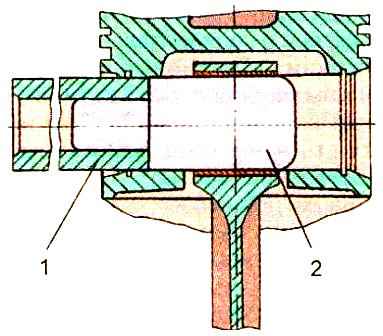
It is recommended to assemble the connecting rod with the piston and pin using a special mandrel shown in fig. 1.
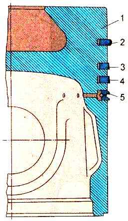
Each piston (fig. 2) is equipped with an upper compression ring, chrome-plated on the outer surface, two (or one) conical compression rings and one box-type oil scraper ring with a spring expander.
Compression conical rings on the end surface near the lock are marked top, which, when installing the rings, should be facing the piston bottom.
The joint of the oil ring expander must not coincide with the ring lock.
Oil scraper piston rings are installed with a mark (pressure) applied on the surface of the ring 7-20 mm from the lock, to the piston bottom.
When the piston is in a horizontal position, the piston rings must move freely, without jamming, in its grooves and sink into them under the influence of their own weight.
Piston ring locks must be spaced equally around the circumference.
The mirror of cylinder liners, pistons with piston rings, connecting rod journals of the crankshaft and connecting rod journals must be lubricated with engine oil.
The locks of adjacent piston rings must be at an angle of 180°.
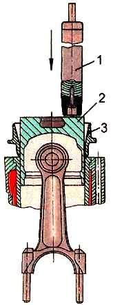
To install the pistons in the block sleeve, you must use the mandrels I806.01.200 and I804.01.200 (Fig. 3).
The tightening torque of the connecting rod nuts should be between 180-200 Nm.
The axial play of the lower heads of the connecting rods on the connecting rod journals is allowed no more than 1 mm at any position of the crankshaft.
The new diesel engine has axial play in the range of 0.15-0.4 mm.
The moment of turning the crankshaft after tightening all the nuts of the connecting rod bolts should not exceed 60 Nm.
In the upper position at TDC, the plane of the bottom of each piston should protrude 0.3-0.55 mm above the upper plane of the cylinder block.
The gap between the piston head and the sleeve at a distance of 3 mm from the upper plane of the block must be at least 0.2 mm.
|
Designation dimensional groups |
Diameter Piston skirts, mm |
Sleeve diameter cylinder, mm |
Gap between piston and sleeve, mm |
|---|---|---|---|
|
B |
110-0.05-0.07 |
110+0.06+0.04 |
0.09-0.13 |
|
C |
110-0.07-0.09 |
110+0.04+0.02 |
0.09-0.13 |
|
M |
110-0.09-0.11 |
110+0.02 |
0.09-0.13 |


