")
")
")
")
")
")
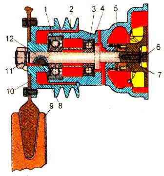
Engine coolant pump
The fluid pump arrangement is shown in fig. 1.
The body of the liquid pump assembly must be tested with water at a pressure of 0.2 ± 0.01 MPa for 2 minutes. In this case, leakage or the appearance of drops is not allowed.
The contact area of the end surface of the support sleeve of the fluid pump housing when checking for paint should be at least 85% with a continuous ring print width of at least 2 mm.
The impeller must be statically balanced. Residual imbalance - no more than 60 g.mm.
The mass should be corrected by drilling in the flat end of holes with a diameter of 8 mm at a radius of not more than 37 mm. Drill exit is not allowed.
The fluid pump pulley must be statically balanced. Residual imbalance - no more than 80 g mm.
The mass should be adjusted by drilling at the end of holes with a diameter of 8 mm at a diameter of 100 mm to a depth of no more than 8 mm.
The thickness of the jumpers between the holes must be at least 5 mm.
The end of the sealing washer during the assembly of the liquid pump must be covered with a thin layer of colloidal graphite lubricant OST 6.08.430-74.
The bearing cavity must be filled with Litol-24 grease weighing 35-40 g.
The nut must be tightened to a torque of 100-120 Nm.
Protrusion of the impeller beyond the end of the liquid pump housing is allowed no more than 0.4 mm, and sinking - no more than 1 mm.
The runout of the conical surfaces of the liquid pump pulley stream is allowed no more than 0.3 mm when the indicator is installed perpendicular to the generatrix of the conical surface.
The end runout of the liquid pump pulley flange is allowed no more than 0.35 mm at the extreme points.
The radial runout of the outer diameter of the fluid pump pulley hub is allowed no more than 0.15 mm.
The fluid pump assembly must be tested for performance at the stand OR-18003-07.
With a pump shaft speed of 2600±20 min -1 and a back pressure of 0.03 MPa, the pump performance should be at least 2.25cm 3/s.
Fan
Riveted fan rivet heads must be at least 3mm high and 7mm in diameter.
A gap between the shank of the cross and the blade at a distance of 5 mm around the rivet shaft is not allowed.
At a distance of 5-10 mm around the rivet shaft, the gap should be no more than 0.1 mm, and at a distance of 5 mm from the inner edge of the blade - no more than 0.2 mm.

The identical side edges of the fan blades must lie in the same plane with a tolerance of 3 mm.
The runout of the side edges of the fan blades is allowed no more than 3 mm at the extreme points.
For one fan, the difference in the width of the blades in the plane of the crosspieces should not exceed 4 mm.
The fan assembly must be statically balanced. Residual imbalance - no more than 250 g-mm.
The mass must be corrected by welding round or rectangular steel plates no more than 1.5 mm thick to the convex surface of the blade, no more than two per blade and no more than two blades.
The fan must be painted in a bright color different from the color of the diesel engine.
Since 1999, diesel engines have been equipped with fans with an uneven X-shaped arrangement of blades, which are completely interchangeable with previously installed fans.
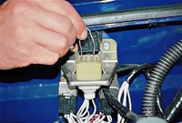
TC-107-04 thermostat
Thermostat with a solid filler, two-valve, type TC-107-04, is located in the outlet pipe of the cylinder head and is connected by hoses to the coolant pump and radiator.

The main thermostat valve starts to open when the coolant temperature is 84-87°C.
At 94°C, it is already fully open.
When the main valve is closed, the liquid in the engine cooling system circulates, bypassing the radiator, through the open additional thermostat valve inside the engine cooling jacket.
When the main valve is fully open, the secondary valve is closed and all the liquid passes through the cooling radiator.
The body heater is connected in parallel with the radiator and the thermostat does not disconnect it from the engine.
Therefore, when the engine is warming up, do not open the air intake damper and turn on the heater motor.
The thermostat automatically maintains the required temperature of the coolant in the engine, turning off and on the circulation of the liquid through the radiator.
In cold weather, especially at low engine loads, almost all heat is removed by blowing cold air into the engine, and the coolant does not circulate through the radiator.
In order to maintain the optimal temperature regime of the engine at negative ambient temperatures, it is necessary to cover the radiator lining with a cover.
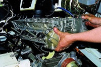
To check or replace the thermostat you need:
Drain approximately 5 liters of liquid from the radiator of the cooling system into a container prepared in advance.
- 1. Loosen the hose clamp.
- 2. Disconnect fluid supply hose.
- 3. Unscrew the four bolts securing the upper cover of the thermostat housing.

- 4. Remove the thermostat from the housing.
Assembly is done in reverse order.
The thermostat must be descaled in a boiling 8-10% alkaline solution for 15-20 minutes, and then rinsed with clean water.
The temperature at the moment the thermostat valve starts to open, placed in gradually warmed up water, should be 84 ° -87 ° С, and at the moment the valve is fully opened - 91 ° - 95 ° С, the lift height of the fully open valve is at least 8.5 mm.
The thermostat valve in the closed position must fit snugly against the seat; allowable gap between valve and seat - 0.1 mm.
The displacement of the valve relative to the neck is allowed no more than 0.5 mm.