")
")
")
")
")
")
Cylinder head and gas distribution mechanism D-245
The cylinder head is a cast iron casting, in the internal cavities of which there are inlet and outlet channels closed by valves
To ensure heat dissipation, the cylinder head has internal cavities in which coolant circulates.
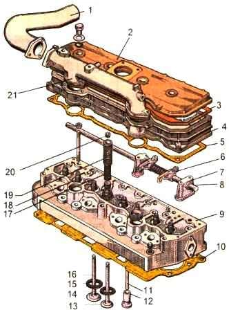
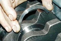
Cylinder head 9 has plug-in valve seats 14 and 15 made of heat-resistant and wear-resistant alloy.
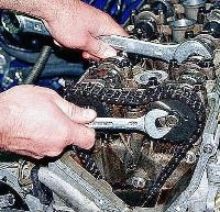
On the top of the cylinder head, racks 7, an axle 8 of rocker arms with rocker arms 6, a head cover 4, an intake manifold and a cap 2 of the cover that closes the valve mechanism are installed.
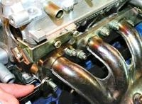
Four injectors are installed in the head on the fuel pump side, and an exhaust manifold is attached to the head on the generator side.
To seal the connector between the head and the cylinder block, a gasket 10 made of asbestos steel sheet is installed.
The holes for the cylinder liners and the oil passage are lined with sheet steel.
When assembling the diesel engine at the factory, the cylinder holes of the gasket are additionally edged with fluoroplastic split rings.
The cylinder head must be cleaned of scale, carbon deposits and washed.
Cracks, leakage of technological plugs are not allowed.
During a hydraulic test of the liquid jacket of the cylinder head under a pressure of 0.40 ± 02 MPa, no leaks or drops are allowed for 3 minutes.
After replacing leaky plugs, the cylinder head should be retested for leaks.
The non-flatness of the surface of the cylinder head to the block must not exceed 0.1 mm over the length of the head (0.05 mm for a new head).
The flatness of the cylinder head to the exhaust manifold must not exceed 0.2 mm over its entire length (0.1 mm for a new head).
The height of the cylinder head must be at least 100.7 mm (103-0.22 mm for a new head).
The threaded holes for the studs in the cylinder head must not be damaged.
The working chamfers of the valve seats and plates must be machined at an angle of 45 + 0.5.
The runout of the surface of the working chamfer of the seat relative to the surface of the guide sleeve after processing should not exceed 0.05 mm.
The runout of the surface of the working chamfer of the valve disc relative to the surface of the rod is allowed no more than 0.03 mm.
The width of the working chamfer of the seat after processing should be 2.0-2.2 mm.
The height of the cylindrical collar of the valve disc must be at least 1.5 mm.
Valve seats cooled down to -120°C must be pressed into the cylinder head heated up to 70°C.
The protrusion of the guide bushing above the plane of the cylinder head, that is, the size from the upper end of the guide bushing to the surface of the recess of the cylinders for the valve springs, must correspond to 33-1.0 mm.
Valves must be lapped and sealed against the seats.
The quality of lapping should be checked by the presence of an annular matte strip on the conical surfaces of the valve and seat.
The width of the strip should be 15…2.0 mm; Strip breaks are not allowed.
The width of the lapped chamfer of the valve seat must be the same along the entire length; the difference in the width of the lapped chamfer of the seat is allowed no more than 0.5 mm.
The strip on the valve should be located no further than 1.0 mm from the edge of the cylindrical band of the valve disc.
The tightness of the fit of the valve disc to the seat should be checked with a pneumatic device KI-16311 - at an air pressure of 0.03-0.05 MPa; air leakage (bubbles) is not allowed.
It is allowed to check the tightness of the valves to the seats by pouring kerosene into the inlet and outlet channels; leakage or the appearance of drops of kerosene from under the valve plates for 2 minutes is not allowed.
After lapping the valves to the seats, the cylinder head and valves should be flushed until the lapping paste is completely removed from the parts.
The valve stems in the guide bushings must move freely, without noticeable lateral wiggle.
The valve stems must be lubricated with engine oil M-10G2 before assembly.
The sinking of the lower planes of the intake and exhaust valve plates relative to the lower plane of the cylinder head should be within 1.05-1.25 mm.
Stubs when installed in the cylinder head, it is allowed to seal with zinc or titanium white.
The ends of the plugs after pressing should not protrude above the plane of the cylinder head.
The non-straightness of the valve stem is allowed along the entire length of no more than 0.022 mm (for a new valve - 0.015).
Cracks and hairlines are not allowed on the surfaces of the valve. 100% of valves are subject to control.
The test should be carried out by the luminescent method.
Valve springs must be subjected to 100% control on a magnetic flaw detector; cracks on springs are not allowed.
The gap between the end and working threads of the valve springs should be no more than 0.3 mm when measured at a distance of 5-10 mm from the end of the coil.
Non-perpendicularity of the supporting surfaces of the valve springs to their axis in the free state is allowed no more than 1° along the length of the springs.
When inspecting the bearing surfaces of the springs, they must be flat on an arc of at least ¾ of the circumference of the end coil.
After screwing the studs into the cylinder head, indentations up to 0.1 mm deep are allowed in areas that do not have threads.
Crackers should protrude above the plane of the valve spring plate no more than 1.4 mm; sink no more than 1.8 mm.
Rock mechanism
The adjusting screws of the rocker arms should be screwed into the rocker arms for the entire length of the thread, and the locknuts should be screwed onto the screws tightly, but without jamming.
The surface hardness of the rocker striker should correspond to 49-57 HRC.
The roughness of the machined surface of the striker should be Ra≤0.3 µm.
The rocker arms must fit snugly against the bearing surface of the cylinder head.
The plugs of the rocker axle - must be tightly wrapped and ensure the tightness of the connections.
The oil channels of the rocker arms and the rocker shafts must be thoroughly cleaned, flushed and blown with compressed air.
The rocker arms should turn freely, without jamming, on the axis of the rocker arms.
The radial runout of the rod rod relative to its spherical surface is allowed up to 0.5 mm.
The non-flatness of the surface of the cover adjacent to the cylinder head and the surface of the cover adjacent to the cap of the cover is allowed no more than 0.25 mm over the entire length.
Intake and exhaust manifolds
The surfaces of the flanges adjacent to the cylinder head must be in the same plane; under a load of at least 300 N, the deviation from flatness is allowed no more than 0.15 mm (for a new flange - 0.1 mm).
Internal surfaces of the intake manifold must be clean, free of carbon deposits and soot.
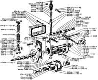
Basic parameters of the head and gas distribution parts

Mounting interfaces of the cylinder head and its parts