")
")
")
")
")
")
Carburettor disassembly 21083–1107010-31
The carburetor is disassembled to clean the carburetor and inspect parts.
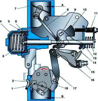
Remove the screws securing the carburetor cover, disconnect the rod 17 (see Fig. 1) for slightly opening the throttle valve of the first chamber and carefully remove the cover so as not to damage the gasket, float and tubes of the econostat and the transition system of the second chamber.
Disassemble the carb cap
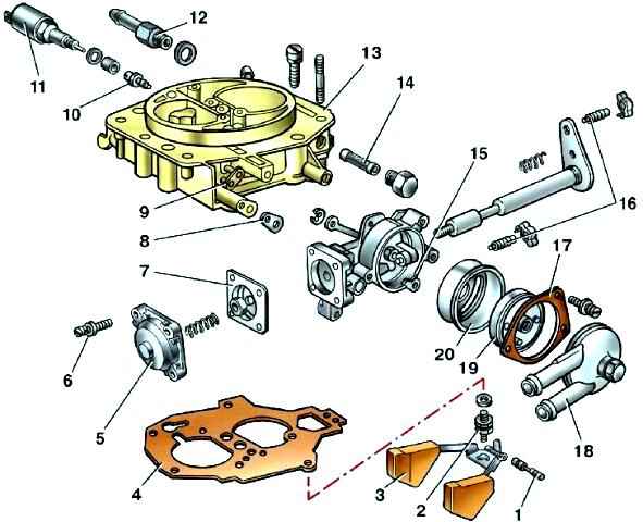
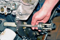
Carefully push the axis 1 (Fig. 2) of floats 3 out of the racks with a mandrel and, without damaging the tongues of the floats, remove them.
Remove the cover gasket 4, unscrew the needle valve seat 2, unscrew the fuel supply pipe 12 and remove the fuel filter 14.
Unscrew the housing of the idle fuel jet 10 with the solenoid shut-off valve 11 and remove the jet.
Remove the mounting screws and remove cover 5 of the semi-automatic trigger.
Remove the lock washer and disconnect the rod from the lever 9 of the air damper.
Unscrew the mounting screws and remove the body 15 of the semi-automatic trigger assembly with the body 19 of the bimetallic spring, the liquid chamber 18 and the drive levers.
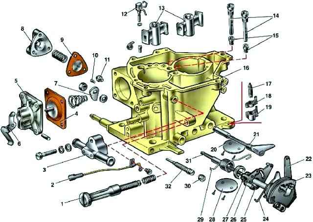
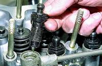
Disassemble the carburetor body (Fig. 3), for which follow these steps.
Disassembly of the semi-automatic launcher is not recommended.
It is strictly forbidden to turn the bimetallic spring of the starting device both in the winding direction and in the opposite direction.
Failure to do so will damage the bimetal spring and cause the carburetor trigger to fail.
Using a screwdriver, remove the return spring bracket and sector 23 by unscrewing the screw securing to the throttle control lever.
Unscrew from the lever 18 (see Fig. 1) the axis of the thrust 17 for slightly opening the throttle valve of the first chamber and disconnect it from the lever.
Remove cover 5 (see Fig. 3) of the accelerator pump with lever 6 and diaphragm 4.
Remove the nozzles 12 of the accelerator pump and the nozzles 13 of the first and second chambers. Take out the nozzles 12 only by the body of the nozzles.
Unscrew the nut of the throttle valve shaft of the first chamber, remove the cam 7 of the accelerator pump drive and the washer.
Remove the fastening screw, remove the electrical wire from the adjusting screw 1 of the idle mixture amount and, if necessary, remove the screw 1.
Remove the plastic plug 30 with a corkscrew and unscrew the adjusting screw 32 of the quality (composition) of the idle mixture.
Remove the power saver cover 8, diaphragm 9 and spring.
Remove the fuel jet 10 of the power economizer, the main air jets 14 with emulsion tubes and the main fuel jets 15 of the main metering systems.
If necessary, unscrew the screws securing the throttle valve 28 of the first chamber, remove the valve and remove the axle assembly with the drive levers.
Having removed the lock washer and unscrewing the fastening screws, remove the throttle valve 20 of the second chamber and remove the damper shaft.
Cleaning and fault detection of the carburetor
- Fuel filter
Wash the filter in gasoline and blow with compressed air.
Check the condition of the filter. If the filter or fuel inlet is damaged, replace it with new ones.
- Float mechanism
Wash the parts in gasoline, check the condition.
Floats must not be damaged.
On the sealing surface of the needle valve and its seat, no damage is allowed that violates the tightness of the valve.
The valve should move freely in its seat, and the ball should not hang.
The weight of the floats must not exceed 6.23 g.
Replace defective parts with new ones.
- Carburettor cap
Clean the cover and all openings and channels from dirt and oil.
Wash the lid in acetone or gasoline and blow with compressed air.
Inspect the sealing surfaces of the lid. If there is damage, replace the cap with a new one.
- Semi-automatic launcher
In order not to disturb the lubrication of bushings, axles and levers, it is forbidden to wash the body of the device and its parts. Jets and emulsion tubes
Clean jets and emulsion tubes from dirt and resinous compounds, wash them with acetone or gasoline and blow with compressed air.
Do not clean the jets with a metal tool or wire, or wipe the jets and other parts of the carburetor with cotton, cloth or rags, as the villi can clog the fuel emulsion path.
In case of severe blockage, you can clean the jets with a soft wood needle moistened with acetone.
- Carburetor body
Clean the body of dirt and oil.
Rinse its channels with acetone or gasoline and blow with compressed air. If necessary, clean the channels and emulsion tubes with special reamers.
Inspect the sealing surfaces of the housing, if they are damaged or deformed, replace the housing with a new one.
- Accelerator pump
Clean the pump parts, wash them in gasoline and blow with compressed air.
Check the ease of movement of the ball in the sprayer and the movement of the moving elements of the pump (lever, diaphragm parts).
Jamming is not allowed.
The diaphragm must be intact, without damage. Check the condition of the sealing surfaces and gaskets.
Replace damaged parts with new ones.
- Power Saver
The diaphragm must be intact and undamaged. If the total length of the diaphragm pusher (including the head) is less than 6.0 mm, replace the diaphragm assembly with the pusher.
Carburetor assembly
Assemble the carburetor in the reverse order of disassembly.
In doing so, pay attention to the following points.
The float should rotate freely on its axis without hitting the walls of the chamber.
The needle valve must slide freely in its seat, without distortion or jamming, the tightening torque should be The la of the needle valve should be 14.7 N (1.5 kgf).
The tightening torque of the solenoid shut-off valve should be 3.68 N (0.4 kgf).
In order not to confuse the jets during assembly, pay attention to the marking of the jets and, when installing them, be guided by table 1 in the article - Carburetor Features 21083–1107010-31
When assembling the accelerator pump, tighten the cover screws, press the drive lever all the way, tighten the screws and release the lever.
When tightening the screws for fastening the throttle valves, emboss the screws along the contour on a special device that prevents deformation of the damper axes.