")
")
")
")
")
")
Features of the carburetor device
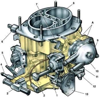
Carburetor 21083–1107010-31 (Fig. 1) emulsion type, two-chamber, with sequential throttle opening.
The carburetor has a balanced float chamber, a crankcase exhaust system for the throttle valve, heating of the first chamber throttle zone.
The carburetor has two main dosing systems of the first and second chambers, an idle system of the first chamber with a transition system, a transition system of the second chamber, an economizer of power modes, an econostat, a diaphragm accelerator pump, a semi-automatic starting device.
The positive idle economizer is activated during over idle.
On vehicles with a fuel flow sensor, a carburetor 2114–1107010-31 is installed, which differs from the basic carburetor in the absence of a fuel drain pipe.
Carburetor 21083-1107010-31 emulsion type, two-chamber, with sequential throttle opening.
The carburetor has a balanced float chamber, a crankcase exhaust system for the throttle valve, heating of the first chamber throttle zone.
The carburetor has two main dosing systems of the first and second chambers, an idle system of the first chamber with a transition system, a transition system of the second chamber, an economizer of power modes, an econostat, a diaphragm accelerator pump, a semi-automatic starting device.
The positive idle economizer is activated during over idle.
Calibration data for the carburetor are shown in Table 1.
Carburetor calibration data 21083–1107010–31
Mixing chamber diameter, first chamber and second chamber 32 mm
Diffuser diameter, first chamber 21 mm, second chamber 23 mm
Main dosing system:
- -marking* of the fuel jet of the first chamber 95, the second chamber 100
- - marking of the air jet of the first chamber 155, the second chamber 125
Emulsion tube type of first chamber 23, second chamber ZC
Idle system and transition systems:
- - marking of the fuel jet of the first chamber 41+3, the second chamber 50
- - marking of the air jet of the first chamber 170, the second chamber 120
Econostat: conditional flow rate** of the fuel jet ─ the second chamber 70
Power Saver:
- - fuel jet marking 40
- - spring compression force with a length of 9.5 mm, N 1.5 ± 10%
Accelerator pump:
- - atomizer marking 35/40
- - cam marking 7
- - fuel supply for 10 cycles, cm 3 11.5±1.75
Starting clearances:
- - air damper (gap A), mm 2.5 +0.2
- - throttle valve (clearance B), mm 1.1+0.05
Needle valve hole diameter, mm 18
Diameter of the fuel bypass opening into the tank, mm 0.7
Diameter of the crankcase ventilation hole, mm 1.5
Fuel level in the float chamber, mm 22.5
Diameter of the balancing holes of the float chamber, mm 4
* The marking of the jets is determined by the flow rate, which is measured using micrometers.
The micrometers are adjusted according to the reference jets.
** The conditional consumption of the fuel jet is determined by the reference jet using a special method.
It is not subject to control during operation.