")
")
")
")
")
")
K-88A carburetor operation in different modes
Idle Mode
The carburetor has two independent idle systems, the same for each chamber
At a low idle speed of the engine, the vacuum from its inlet pipeline is transmitted through the holes of round 43 and rectangular 42 sections and channel 44 (Figure 2).
Under the action of vacuum, the fuel from the carburetor float chamber, passing jet 47, is directed to idle jet 6.
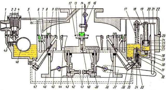
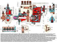
K88 carburetor: 1 - air inlet body; 2 - needle valve for fuel supply; 3 - mesh filter; 4 - filter plug; 5 - channel for balancing the float chamber; 6 - idle jet; 7 - cavity; 8 - full power jet; 9 - air jet; 10 - small diffuser; 11 - annular gap; 12 - nozzle; 13 - air cavity; 14 - hollow screw; 15 - air damper; 16 - automatic valve; 17 - pusher; 18 and 34 - spring; 19 and 21 - rods; 20 - bar; 22-ring groove; 23 - body of the float chamber; 24 - cuff; 25 - cuff spring; 26 - stem bushing; 27 - hole; 28 - intermediate pusher; 29 - ball inlet valve; 30 - saddle; 81 - ball valve; 32 - thrust; 33 mechanically driven economizer valve; 35 - fuel channel; 36 - cork; 37 - lever; 38 - gasket; 39 - channel; 40 - needle discharge valve; 41 - idle adjustment screws; 42 - rectangular hole; 43 - hole of the idle system; 44 - channel; 45 - throttle valve; 46 - body of mixing chambers; 47 - main jet; 48 - float; 49 - float spring
To obtain the required composition of the mixture, the air entering the jet 6 through the cavity 7 is mixed with the fuel.
The resulting emulsion flows through the round hole 43 and the rectangular hole 42 into the mixing chamber.
When leaving the holes, the emulsion mixes with the main air flow passing through the chamber through the slot formed by the edge of the throttle valve 45 and the wall of the housing 46 of the mixing chambers.
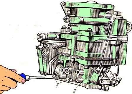
Idling is regulated by a stop screw 2, which limits the closing of the throttle valves, and two screws 1, which change the composition of the combustible mixture.
Idle speed can only be adjusted when the engine is fully warmed up and the ignition system is in perfect working order.
Special attention should be paid to the serviceability of the candles and the correct gap between their electrodes.
It should be taken into account that the carburetor is two-chamber, and the composition of the mixture in each chamber is regulated independently of the mixture composition of the other chamber with the corresponding screw 41; in addition, it must be remembered that when screws 41 are screwed in, the mixture is leaner, and when they are unscrewed, it is enriched.
Starting the adjustment, it is necessary to turn the screws 41 until they stop, but not too tight, and then unscrew each one by three turns.
After that, you need to start the engine and set the stop screw to the smallest throttle opening at which the engine runs quite stably.
Then it is necessary to lean the mixture using one of the screws 41, turning this screw ¼ turn at each test until the engine starts to work with obvious interruptions due to excessive lean mixture in the cylinders.
Then enrich the mixture by turning screw 41 ½ turn.
After finishing adjusting the composition of the mixture in one chamber, it is necessary to perform the same operations with the second screw 41.
After adjusting the composition of the mixture, you should try to reduce the idle speed by unscrewing the throttle stop screw a little, after which you should again try to lean the mixture using screws 41, as indicated above.
It usually takes two or three attempts to find the correct position for all three adjustment screws.
You should not set the idle speed too low, to check the idle speed adjustment, press the throttle pedal and immediately release it sharply.
If the engine stops running, increase the idle speed.
A properly adjusted carburetor should ensure stable operation of a serviceable engine idling at 400-500 rpm.
Partial load mode
As the throttle opening increases, the amount of air passing through the main air passage increases, resulting in a vacuum in a small diffuser 10 is sufficient for the main dosing system of the carburetor to come into operation.
In this case, fuel from the float chamber flows through jets 8 and 47 to the annular slot 11 of the small diffuser.
When the fuel moves, a small amount of air is mixed with it, passing through the air jet 9.
As a result, an emulsion is formed and at the same time the vacuum around jets 8 and 47 is reduced; this achieves the required mixture compensation.
At light to medium engine loads, the mechanically operated economizer valve is closed and the carburetor supplies an economical mixture.
Full load mode
The mechanically operated economizer valve 33 is closed by a spring 34 which presses the ball valve 31 against the seat 30.
The valve opens when the throttle valve is in a position close to its full opening, due to the kinematic connection of the valve with lever 37, rod 32, stem 21 and bar 20.
In this case, the bar 20, fixed on the rod 21, through the pusher 17 comes into contact with the intermediate pusher 28 and moves it down.
The intermediate pusher presses the valve 31, and it moves away from the seat. Fuel passes through opening 27 and enters the main fuel channel 35.
Fuel is metered by the economizer valve jet, and then goes to the full power jet, the flow section of which is designed to prepare a mixture that ensures full engine power.
Acceleration mode
The enrichment of the mixture, which is necessary when the throttle is suddenly opened, occurs with the help of an accelerator pump, the drive of which is combined with a mechanical drive of the economizer valve.
When the damper is closed, the piston of the accelerator pump, consisting of the sleeve 26 of the rod, the spring 25 and the cuff 24, is in the upper position, and the cavity below it is filled with fuel from the float chamber through the ball inlet valve 29.
When the throttle valves are suddenly opened, the lever 37 turns and lowers the piston drive together with the bar 20.
There is a hole in the bar, into which the pump piston rod 19 freely enters.
The bar, lowering, compresses the spring 18, which causes the pump piston to move downwards, the inlet ball valve 29 is pressed against the seat in the body of the float chamber, and the fuel flows through the channel to the holes in the hollow screw 14, opening the needle valve 40 along the way.< /p>
Then the fuel comes out in the form of thin jets from the nozzle 12, hits the walls of the diffusers, breaks into tiny particles and, mixing with air, is sent to the engine intake gas pipeline.
As a result of the elastic connection of the piston of the accelerator pump with the throttle valve with the help of spring 18, a protracted fuel injection is obtained and, in addition, the action of the pump, which slows down the opening of the damper, is eliminated.
The accelerator pump drive is designed so that the pump operates in the first half of the throttle opening.
The needle valve 40 and the air cavity 13 in the injector body 12 prevent the flow of fuel through the accelerator pump system during engine operation at high speeds with a constant throttle position.
Starting a cold engine
The start is carried out using the air damper 15 and the accelerator pump.
The air damper is controlled from the driver's cab.
To improve the starting qualities of the engine, the design of the carburetor provides for communication with the air and throttle valves, as a result of which, when the air damper is fully closed, the throttle valves open a small amount.
Carburetor care and adjustment
In the terms specified in the article - "Maintenance of the car", it is necessary to remove the sediment from the carburetor and clean it.
It is necessary to flush the carburetor in clean gasoline or acetone, followed by blowing with compressed air.
A fuel supply valve and an economizer valve with an elastic locking element (made of special rubber) can be installed in the carburetor, so flushing with acetone or solvents based on it should be carried out only after these assemblies have been unscrewed from the carburetor body parts.
Knocking on the valve and compression of the seat with the valve is not allowed.
When disassembling the carburetor, removing the upper housing, it is necessary to unscrew the hollow screw 14.
It must be taken into account that the discharge needle valve 40 is not secured and may fall out of the body.
It is strictly forbidden to use wire or any metal objects to clean jets, nozzles, channels and holes.
It is forbidden to blow compressed air through the assembled carburetor through the fuel inlet and balance tube, as this will damage the float.
When storing carburetors for a long time, care must be taken to protect them from corrosion, contamination and damage.
Pneumatic Intrigible speed limiter
The maximum number of revolutions of the engine crankshaft is limited by a pneumatic centrifugal limiter, consisting of two mechanisms: a centrifugal sensor rotating from the engine camshaft and a diaphragm actuator that acts on the carburetor throttle valves.
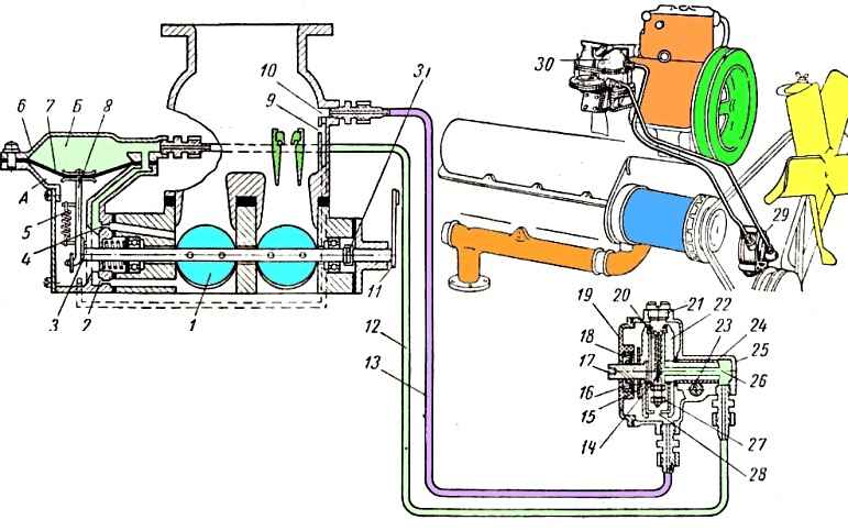
The sensor consists of three main parts: body 25, cover 19 and rotor 22. The cover is connected to the body with screws; for sealing, a gasket is installed between them.
There is a sealing gland 18 in the cover.
A ceramic-metal porous sleeve 24 is pressed into the sensor housing, for lubrication of which a wick 23 soaked in oil is provided.
A valve 27, a valve seat 28, an adjusting screw 20 and a spring 14 are installed in the sensor rotor. To access the adjusting screw, the sensor housing has a hole closed with a plug 21.
The sensor must be lubricated in accordance with the lubrication chart.
When the engine is running, a vacuum is transmitted from the mixing chamber through jets 2 and 4 to cavity "B", under the influence of which air begins to flow from the carburetor air neck through hole 10.
Air passes from the air inlet into cavity "B" through hole 10, tube 13 connecting the carburetor air inlet with the side opening of the sensor housing, hole in the valve seat 28, channel 26 in the rotor axis, tube 12 connecting the central hole of the sensor housing with diaphragm cover.
The vacuum created in this case in the cavity "B" above the diaphragm is small, and the throttle shaft freely rotates in the direction of their opening under the action of spring 5.
If a certain number of revolutions, to which the centrifugal sensor is adjusted, is exceeded, the valve 27, under the action of centrifugal force, overcomes the tension of the spring 14 and partially closes the hole in the valve seat 28, thereby changing the air flow from the air inlet to the cavity "B" above the diaphragm .
The vacuum from the mixing chamber through jets 2 and 4 is completely transferred to the space above the diaphragm, as a result of which the diaphragm moves upward, overcoming the tension of spring 5 and closing the throttle.
Cavity "A" is connected through hole 9 with the air inlet of the carburetor.
When the throttle valves are closed, the flow of the combustible mixture into the engine cylinders is reduced, as a result of which the engine does not exceed the specified speed.
The speed limiter is set at the factory to the specified maximum speed and must not be changed in service.