")
")
")
")
")
")
Installing cylinder liners
Cylinder liners and the seating surfaces of the cylinder block under the liners should be wiped with a napkin and blown with compressed air
Install the cylinder liners in the diesel block
The protrusion of the cylinder liner flanges above the plane of the block when the liner is pressed with a force of 9 ± 0.1 kN should be 0.05-0.11 mm.
For details on the installation of liners, see the article - Replacing the cylinder liners of the D-245 diesel engine
Laying the crankshaft
Before assembly, each crankshaft must be checked on a magnetic or ultrasonic flaw detector for the absence of micro and macrocracks, as well as for the compliance of the selected set of main bearing shells with the size of the main journals.
We look in detail at the article - Laying the crankshaft of the D-245 diesel engine.
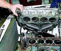
Installing the connecting rod and piston group
Check whether the size group of the piston set and the size group of the cylinder liners match.
Pistons of one set on a diesel engine must be of the same size group corresponding to the size group of cylinder liners.
We look in detail at the article - Installation of pistons and rings for diesel D-245.
Installing the gas distribution mechanism
The switchboard gasket must not show visible damage.
Nicks and other mechanical damage to the treated surfaces of the distribution board are not allowed.
See the article in detail - Installing the gas distribution mechanism D-245.
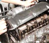
Installing the cylinder head and valve train
We look at the installation of the cylinder head in the article - Installation of the cylinder head and valve mechanism D-245
Installation of injection pump, injectors, high and low pressure pipes
The mounting plate of the injection pump must be clean; nicks and other damage to the slab are not allowed.
The fuel pump gasket must not show visible damage.
When installing the fuel pump, match the marks of the gear wheel of the fuel pump drive and the splined flange.
The splined flange of the fuel pump gear must be free, without jamming, on the splines of the fuel pump shaft bushing.
The bolts of the fuel pump gear flange must be tightened to a torque of 18-25 Nm.
Injectors of the same group must be installed on a diesel engine.
Sealing gaskets on the side adjacent to the nozzles must be lubricated with grease.
The injector mounting bolts must be tightened to a torque of 20-25 Nm.
High pressure pipes must be fixed at a distance of 10-15 mm from the union nuts with clamps with gaskets.
Pipes of low fuel pressure should be blown out with compressed air before installation on a diesel engine.
In detail, you can see the article - Installation of injection pump for diesel D-245
Installing the oil pump and power steering pump housing
Before installing the oil pump, check the ease of rotation of the gears.
The oil pump guide pins must fit snugly into the holes in the first main bearing cap.
It is necessary to put lock washers under the oil pump mounting bolts.
The side gap between the teeth of the oil pump drive gears should be within 0.1-0.65 mm.
The bolts securing the outlet pipe to the oil pump and the cylinder block must be tightened to a torque of 15-25Nm.
The power steering pump housing must be flushed and blown out with compressed air before installation.
The side gap between the teeth of the gear wheels of the hydraulic pump drive should be within 0.08-0.2mm.
The housing of the drive, hydraulic pump after installation on a diesel engine must be closed with a cover with a gasket.
The oil pump delivered to the diesel assembly must be run in and tested.
See the article in detail - Requirements for the D-245 diesel oil pump
Installing the oil receiver
Before installation, the oil receiver must pass a hydraulic test with diesel fuel or an air test under a pressure of 0.1 ± 0.02 MPa.
Leakage, leakage or leakage of air at the junction of the pipe and flange is not allowed.
Sags and irregularities after welding must be cleaned.
Installing the oil sump
Seals must be installed in the grooves of the oil sump support before assembly.
Before installing the oil sump, trim the protruding ends of the gasket between the distribution cover and the plane of the block.
The plane of contact of the oil sump to the block before installing the gasket must be lubricated in three places with paste UZOM GOST 13489-79.
Nicks and dents with a width of more than 0.1 mm on the treated surfaces of the oil sump are not allowed.
Installing the rear sheet, cuff housing and crankshaft flywheel
The rear sheet should sit snugly on the pins pressed into the cylinder block.
The rear sheet and the plane of mating with the crankcase, as well as the surface of the flywheel and the crankshaft flange must be wiped with a clean cloth.
Paronite gaskets of the rear sheet and cuff body before installation on the pins you need to grease with paste on both sides.
The mating surfaces of the flywheel and the crankshaft flange must not have nicks, burrs or other damage.
The flywheel mounting bolts should be tightened evenly in several steps.
The final tightening of the flywheel mounting bolts must be carried out with a torque of 180-200 Nm.
Installing the diesel support and the crankshaft pulley
The crankshaft pulley should be wiped with a clean cloth.
There should be no nicks or burrs on the seating and working surfaces of the bearing and the crankshaft pulley.
The crankshaft pulley bolt must be tightened with a torque of 240-280 Nm.
Installing a centrifugal oil filter (centrifuge)
The mating surfaces of the block and the centrifuge must not have nicks or other damage.
The mating surfaces must be wiped with a clean cloth before installing the centrifuge.
The gasket of the centrifuge should not have any tears or irregularities.
The centrifuge mounting bolts must be tightened to failure, having previously installed gaskets.
Installing the Fluid Pump Assembly and Thermostat
The roller of the liquid pump should rotate smoothly by hand without jamming the impeller.
The fluid pump gasket must not have tears or delaminations.
The gasket must be lubricated on both sides with UZOM paste before being installed on the liquid pump.
There must be no mechanical damage on the mating plane of the thermostat housing with the cylinder head.
Before installing the thermostat housing, the mating surface with the cylinder head must be wiped with a clean cloth.
The thermostat housing gasket must be lubricated on both sides with UZOM paste before installation.
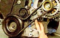
Installing the alternator, fan and fluid pump drive belt
The grooves of the pulleys of the generator and the liquid pump must be located in the plane of the grooves of the crankshaft pulley with a tolerance of ± 1.5mm.
Nicks and burrs are not allowed on the mating surfaces of the fluid pump pulley and the fan cross.
For the procedure for installing the generator and tensioning the belt drive, see the article "Electrical Equipment".
Starter installation
The mating surfaces of the starter and rear sheet must be free of nicks and burrs.
Wipe the mating surfaces of the starter and rear sheet with a clean cloth.
A gap between the starter surface and the backsheet is not allowed.
Compressor installation
The dowel pins pressed into the distribution cover must be a tight fit.
The compressor gasket must be flat, without tears or delaminations.
Pre-tightening the bolt of the oil pipe fitting and compressor mounting should be done no more than 3 threads.