")
")
")
")
")
")
Before assembly, the low-pressure cavity of the pump must be flushed with diesel fuel at a pressure of 1.8-2.0 MPa
To lubricate parts of the pump and regulator, use filtered engine oil M10G2
Plunger pairs and pressure valves must be thoroughly flushed with filtered diesel fuel.
When assembling the rotary sleeves of the plunger with plunger pairs, the movement of the plunger in the grooves of the rotary sleeve must be free, without jamming and sticking.
When installing the swivel sleeve of the plunger assembly with the ring gear in the pump, the screw head of the ring gear must face the middle of the manhole.
In this case, the gap in the ring slot must be at least 0.5 mm with the ring gear screw tightened.
Installed in the pump, the rotary sleeve of the plunger assembly with the gear rim, when the screw of the gear rim is tightened, must rotate freely on the plunger sleeve, jamming is not allowed.
When assembling the lower plates of pusher springs with plungers, the plunger shank with its cylindrical surface with a diameter of 6.2 mm must freely pass through the slot in the plate, the bearing foot of the plunger shank should be buried in the undercut of the plate with a diameter of 11.5 +0.27mm.

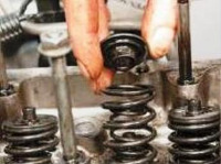
When assembling pushers 4 (see Fig. 1), the roller axis must rotate freely in the holes of the pusher body, the pusher roller must rotate freely on the bushing, and the bushing on the roller axis.
Jamming in the mate of the specified parts is not allowed.
The pushers, previously lubricated with clean engine oil, should move easily, without jamming and sticking, under the action of their own weight in the body bores.
When installing the rack into the pump housing, the guide bushings and the rack must be lubricated with clean engine oil.
The movement of the rack in the pump housing should be easy and smooth, jamming is not allowed.
When installing swivel bushings of the plunger assembly with ring gears, the slots of the ring gears must be installed perpendicular to the sides of the pump.
In this case, the distance from the inner side of the rack pin to the pump housing should be 16 ± 0.5 mm.

After installing the pins that fix the plunger bushings, you should check the mobility of the rail.
The rail should move easily, without tangible jamming. Sharp, jerky movements of the rack are not allowed.
After installing the discharge valves in the pump housing, a gasket must be installed on the discharge valve seats with a conical surface upwards.
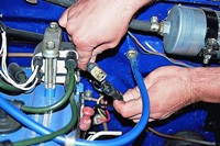
The fuel pump fittings should be tightened to a torque of 98-108 Nm, having previously been lubricated with filtered diesel fuel or oil.
After installing the springs, pushers and lower plates, you need to check for:
- - no pinching of the plunger shank between the pusher bolt and the lower plunger plate;
- - smoothness of rail movement;
- - ensuring the clearance above the plunger at the extreme upper position of the pusher, which must be at least 0.3 mm.
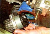
Before installation, the camshaft bearings must be lubricated with engine oil.
The bearings must be pressed onto the journal of the camshaft with a diameter of 20 mm until it stops, distortions are unacceptable.
Before installing the camshaft in the pump housing, it is necessary to check the condition of the bearing rings and separators.
Damage of separators and loss of rollers are not allowed.
The camshaft nut must be tightened to 43 Nm and secured with a lock washer.
The folded surfaces of the lock washer are allowed to be indented by the crimper, but not to burr.
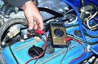
After installing the camshaft in the pump housing, measure the axial force applied to the shaft from the side of the regulator.
When moving the camshaft from 0.02 to 0.1 mm, it must be at least 450 N.
With a further increase in the load on the camshaft, its additional movement by at least 0.5 mm must be ensured.
With a force of less than 442 N, the required number of shims must be installed under the outer ring of the bearing in the bearing cup.
The installation of one shim increases the axial force at 24.5-29 N.
The axial force on the camshaft is measured when there is no load on the camshaft from the pushers.
It is allowed to measure the axial force on the cam shaft with the pushers lowered. In this case, the minimum axial force applied to the shaft must be at least 638 N.
When adjusting the axial force, it is strictly forbidden to hit the camshaft nut, the camshaft shank from the side of the regulator or the bearing cup with a hammer.
When adjusting the axial force on the camshaft, ensure that there is a gap between the priming pump housing and the second and third cams of the camshaft.
The clearance must be ensured by installing shims in the bearing cup or by shifting them from the bearing cup to the mounting flange.
The two upper bolts of the mounting plate must be placed on the anaerobic sealant UG-11.