")
")
")
")
")
")
All parts of the regulator must be clean before assembly, and the rubbing surfaces lubricated with engine oil
The presence of traces of corrosion and dirt on the surface of parts and wiping them with cleaning material is not allowed.
At the beginning of the assembly, it is necessary to press the thrust washer until it stops. When rotating the camshaft of the pump, touching the thrust washer on the bearing cup is not allowed.
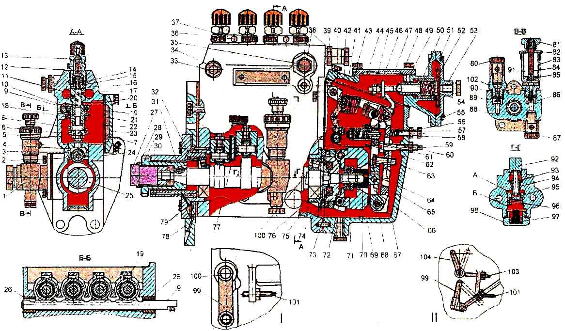
High pressure fuel pump: I - version of a single-lever injection pump; II - a variant of a double-lever injection pump; 1 - fuel priming pump; 2 - pusher roller bushing; 3 - pusher roller; 4 - plunger pusher; 5 - pusher adjusting bolt with locknut; 6 - bottom plate; 7- plunger shank; 8 - plunger spring; 9 - rail; 10 - ring gear; 11 - fuel outlet channel; 12 - pressure valve spring; 13 - fitting; 14 - discharge valve; 15 - gasket; 16 - discharge valve seat; 17 - fuel supply channel; 18 - plunger bushing; 19 - coupling screw; 20 - pin; 21 - top plate; 22 - rotary plunger sleeve; 23 - cover; 24 - injection pump housing; 25 - cam shaft; 26 - rack nut; 27 - nut; 28 - washer; 29 - slotted sleeve; 30 - mounting flange; 31 - key; 32 - spring; 33 - air outlet plug; 34 - futorka; 35 - bypass valve; 36 - bolt; 37 - clamp; 38 and 102 - futorki: 39 - boost corrector housing; 40 - spring lever; 41 - spring starting enricher; 42 - finger; 43 - earring; 44 - regulator spring; 45 - rack rod; 46 - emphasis; 47- cover of the boost corrector; 48 - the main lever of the regulator; 49 - pin; 50 - bushing; 51 - diaphragm; 52 - plate; 53 - boost corrector cover; 54 - stock; 55 - screw; 56 - bolt; 57 - idle spring; 58-corrector rod; 59 - shims; 60-hard stop; 61 - corrector housing; 62 - bracket; 63 - bolt; 64 - heel; 65 - axis of the intermediate lever; 66 - intermediate lever; 67 - body of the speed controller; 68 - axis of levers; 69 - cargo; 70 - regulator clutch; 71 - adjusting screw; 72 - cargo axis; 73 - hub; 74 - elastic drive rubber elements; 75 - thrust washer; 76 - bearing glass; 77 - plate retainer; 78 - pump mounting plate; 79 - bearing; 80 - square bolt; 81 - handle - nut; 82 - cover; 83 - vertical cylinder; 84 - stock; 85 - piston of the fuel pump; 86 - inlet nylon valve; 87 - swivel square; 88 - body; 89 and 96 - springs; 90 - Discharge valve; 91 - fuel pump; 92 - pusher; 93 - guide sleeve; 94 - rod; 95 - piston of the fuel pump; 97 - emphasis; 98 - cork; 99 - fuel control lever; 100 - control lever roller; 101 - screw for adjusting the maximum speed; 103 - screw for adjusting the diesel stop lever; 104 - diesel stop lever
When assembling loads with a hub, the ends of the axles of the loads must be flared.
The protrusion of the flared part of the axles should be no more than 0.5 mm.
Loads must swing freely on their axles.
Jamming and sticking are not allowed.
At the ends of the load axis, 1-2 metal breaks from flaring are allowed.
Only one group of weights can be installed in the regulator.
Belonging to the first or second group of goods is marked with paint on their outer surfaces:
- - white - second group;
- - red - first group.
When assembling a governor with a thrust bearing, a thrust bearing 8110 must be installed on the weight hub, the inner ring of which must be pressed against the stop into the shoulders of the hub.
The bearing needs to be lubricated with engine oil.
In the inner cavity of the hub, install crackers, which must be lubricated with engine oil, and put the assembled unit on the camshaft of the fuel pump so that the protrusions of the thrust washer enter between the crackers.
When installing a new bearing, it is necessary to depreserve it, followed by lubrication with engine oil.
The retaining spring ring must lie tightly in the annular groove of the camshaft, while there must be a guaranteed gap between the spring ring and the weight hub.
Before installing the governor clutch with thrust bearing, press the inner ring of the thrust bearing onto the clutch, while the ring is not distorted.
When installing the governor clutch, the rotation of the outer race of the bearing and the free movement of the clutch on the camshaft shank must be ensured.
The bearing is lubricated by pouring grease in the amount of 150-200 ml into the regulator before installing it on the stand for adjusting the fuel pumps.

Before installing the corrector in the regulator, you should first adjust the stroke of the corrector in the range of 0.5-0.7 mm.
The course of the corrector is finally adjusted on the stand to ensure the specified fuel supply according to the adjustment table.
The main and intermediate levers installed in the regulator body should swing freely on the axle without jamming.
It is not allowed to touch the bolt of the main lever with the groove of the intermediate lever.
Bolt 56 (see Fig. 1), which limits the travel of the levers, must be placed on the KLT-75T compound.
From the inside of the regulator, screw the idle spring onto the bolt.
Hard stop 60 should also be placed on the KLT-75T compound.
The bolt must be screwed in until its outer end protrudes 12-13 mm above the surface of the boss of the regulator body and locked with a nut.
When installed in the regulator housing, the collar of the enricher roller must be lubricated with engine oil.
When installing the control lever into the regulator housing, the lever shaft must be lubricated with engine oil.
The adjusting screw, located on the side of the regulator, must be screwed into the eye until its end protrudes above the surface of the eye by approximately 17 mm and is locked (measured from the rear wall of the regulator).
In the assembled regulator, touching the regulator spring on the intermediate lever throughout the entire length of the control lever stroke is not allowed.
Before installing the regulator housing assembly on the pump housing, you must:
- check the presence of cotter pins in the nodes of the regulator; to connect the rack rod with the pin of the intermediate lever, it is allowed to apply the KLT-75T compound to the mating surfaces of the pump housing and the regulator housing (after degreasing them first) instead of the gasket.
When installing the regulator housing assembly on the pump housing, the regulator housing must fit snugly, without distortion, on the pump housing pin.
In the assembled regulator, all parts should move without jamming.
With the maximum deviation of the intermediate lever forward, it is not allowed to rest the adjusting screw of the corrector against the spring lever.
The pump should be run-in in cases of replacing the pump housing, regulator housing, plunger pair, pushers, plunger springs, regulator coupling, fuel priming pump, camshaft, as well as when fuel ingress into the pump housing is detected more than the permissible value.
The run-in should be carried out with injectors, the springs of which are tightened to an injection start pressure of 12-17 MPa, at a rotation frequency of 750 min-1 for 40 minutes.
Running is performed with a variable position of the control lever.
During the running-in process, it is necessary to observe the normal operation of all components and mechanisms of the pump and regulator.
After running-in, the following screw connections should be checked and, if necessary, tightened:
- - bolts for fastening the fuel priming pump;
- - regulator mounting bolts;
- - bolts for fastening the plate and mounting flange;
- - fitting clamps.