You will need:
- a torque wrench, a hammer, a device for installing pistons in cylinders, keys "for 10", "for 13", "for 14", "for 17", "for 19", "for 21", "for 22 ”, “36” (or gas), socket heads “12” and “13” (or a special key for cylinder head bolts), screwdriver, mounting blade
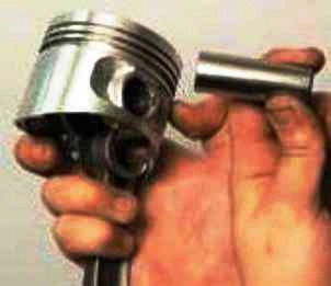
Place the piston on the connecting rod, making sure that the hole for the pin coincides with the hole in the upper head of the connecting rod.
Use your hand to push your finger, lubricated with engine oil, into the holes of the piston and connecting rod.
Insert the retaining rings into the grooves of the piston bosses and additionally lubricate the finger with engine oil through the holes in the piston bosses.
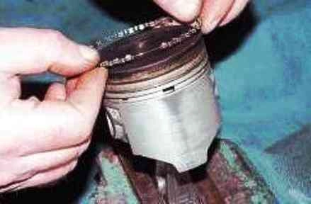
Install the piston rings in the reverse order of removal.
When installing, do not expand the rings more than necessary so as not to deform or break them.
Install the lower compression ring with the undercut (shown by the arrow) down into the second groove.
If the ring is marked "Top" or "TOP", then install the ring with the mark up (towards the piston bottom).
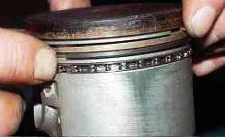
Orient the rings. Install the rings on the remaining pistons.
Orient the rings as follows:
- - the lock of the upper compression ring should be located at an angle of 30–45 ° to the axis of the piston pin;
- -lock of the lower compression ring - at an angle of approximately 180° to the axis of the lock of the upper compression ring;
- - oil scraper ring lock - 90° to the axis of the upper piston ring lock.
Lay the upper main bearing shells (with grooves) in the bed of the cylinder block.
Install the inserts so that the insertion tab of the insert is aligned with the notch on the bed.
In the bed and the cover of the middle bearing, lay the liners of a larger width (without a groove).
Lubricate the liners with engine oil.
Install the crankshaft into the cylinder block.
Place the lower (without groove) shells in the main bearing caps.
Lubricate the crankshaft journals with engine oil.
Lubricate the liners in the crankshaft main bearing caps with engine oil.
Install the caps (except the rear) of the main bearings and lubricate the thrust half rings with engine oil.
Install the covers in the same block in accordance with the marks, orienting them in the same direction as before disassembly.
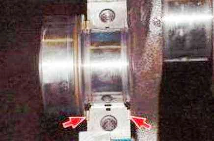
Install the rear (ceramic, yellow) and front (steel-aluminum) thrust half rings of the rear crankshaft support.
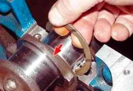
Install thrust washers with notches to the bearing surfaces of the crankshaft
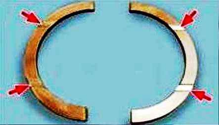
Install the rear main bearing cap and cap bolts and tighten with a torque wrench.
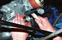
Check the end clearance of the crankshaft with a flat feeler gauge by moving the crankshaft with a mounting spatula until it stops. The axial clearance should be 0.06–0.26 mm.
The maximum allowable gap is 0.35 mm.
If the gap is larger, replace the thrust half rings with others increased by 0.127 mm.
Check for proper assembly by turning the crankshaft a few turns by hand.
The shaft should rotate freely and smoothly.
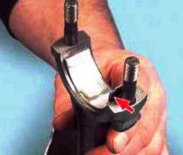
Insert the connecting rod bolts (if they were removed) and the bushings into the connecting rods, aligning the mounting tab of the bushing with the notch on the connecting rod.
Lubricate the cylinder bores, pistons, piston rings and connecting rod bearings with engine oil.
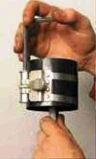
put the ring compression tool on the piston and, turning the screw, compress the rings.
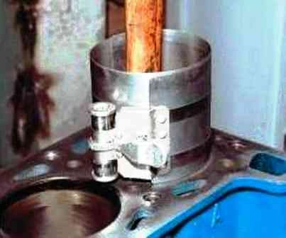
Install the piston into the cylinder according to the cylinder number marking on the connecting rod, press (e.g. with a hammer handle) the piston and slide it from the mandrel into the cylinder.
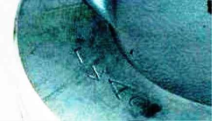
Similarly, install the pistons in the remaining cylinders.
When installing pistons into cylinders, the arrow on the piston must point towards the front of the engine
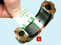
Install the connecting rod bearings into the connecting rod caps, aligning the insertion tab of the bearing with the notch on the cap.
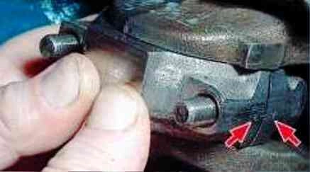
Lubricate the connecting rod bearings in the connecting rod caps and crankshaft journals with engine oil.
Install the connecting rod cap by connecting the connecting rod to the crankshaft journal and aligning the marks on the connecting rod and cap.
Tighten the nuts of the connecting rod bolts without completely tightening them. Install the other connecting rod caps in the same way.
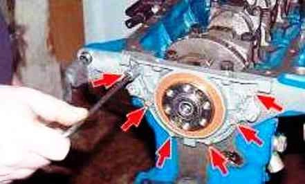
Tighten the connecting rod bolt nuts with a torque wrench.
Install the crankshaft rear oil seal holder, replacing the gasket.
Center the holder relative to the shaft flange with a special mandrel (if not, center the holder along the working edge of the stuffing box) and tighten the six bolts of the holder, aligning the plane of the holder with the plane of the block connector without distortion.
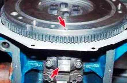
Install the flywheel (after installing the front cover of the clutch housing) so that the mark (cone-shaped hole) near the rim is against the axis of the connecting rod journal of the fourth cylinder, and secure the flywheel by tightening its fastening bolts.
Install the parts and assemblies in the sequence corresponding to the listing: sprocket on the crankshaft, oil separator, oil pump drive gear, oil pump drive shaft, oil pump (replacing the gasket), oil crankcase (replacing the gasket and not finally tightening its fastening bolts) , block head (replacing the gasket).
Tighten the head bolts in four steps in a specific sequence (see How to replace cylinder head gasket VAZ-2123).
Install the sprocket onto the camshaft assembled with the bearing housing and rotate the shaft so that the mark on the sprocket is opposite the mark on the bearing housing.
Remove the sprocket and, without changing the position of the shaft, install the bearing housing on the cylinder head.
Fix the housing by tightening the nuts in a certain sequence (see How to replace the camshaft VAZ-2123).
Install the chain tensioner shoe.
Turn the crankshaft so that the mark on the crankshaft sprocket aligns with the mark on the cylinder block.
Put the chain on the sprocket without changing the position of the crankshaft.
Put the chain on the sprocket of the oil pump drive roller and, pulling the drive branch, install the sprocket on the roller without completely tightening the bolt of its fastening.
Attach the wire to the chain and lift the chain up in the drive cavity (or hook it on top and lift it up).
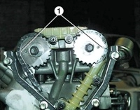
Put the chain on the camshaft sprocket, tension the drive branch and install the sprocket on the shaft, ensuring that the mark on the sprocket and the lug on the bearing housing match and do not completely tighten the bolt of its fastening.
Install the chain tensioner (if removed when disassembling the cylinder head).
Turn the crankshaft two turns in the direction of rotation to obtain the correct chain tension.
Check that the marks on the sprockets match the marks on the cylinder block and on the bearing housing at the same time.
If the marks do not match, reinstall the chain.
If the marks match, finally tighten the sprocket bolts and fold back the ends of the sprocket bolt lock washers. Install the head cover by replacing the gasket.
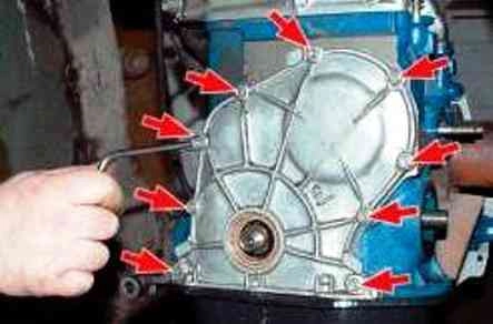
Install the camshaft timing chain cover with the front crankshaft oil seal, replacing the gasket.
Center the holder relative to the shaft flange with a special mandrel (if there is no mandrel, center the holder along the working edge of the stuffing box, temporarily installing pulleys on the crankshaft shank) and tighten the bolts and nuts securing the cover.
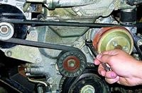
The bolts that simultaneously secure the power steering pump bracket must be tightened after the pump is installed.
Finally tighten the oil sump mounting bolts. Install the crankshaft pulleys.
Install the rest of the parts and assemblies in the reverse order of removal.
Run the engine in the following sequence:
Make sure that the throttle actuator is adjusted correctly, fill in oil and coolant, check the tightness of all connections.
Start the engine and let it run unloaded for the next cycle.
|
Frequency Crank shaft, min-1 |
Time work, min |
|---|---|
|
820-900 |
2 |
|
1000 |
3 |
|
1500 |
4 |
|
2000 |
5 |
Do not bring the engine to maximum speed.
During operation, check the tightness of the engine and its systems, oil pressure, ignition setting, idle speed, pay attention to the presence of extraneous noise.
If abnormal noises or other malfunctions are found, stop the engine and eliminate their cause.
After starting the operation of the car, follow the regimes provided for the break-in period of a new car.


