")
")
")
")
")
")
Generator G250P2 and generators 665.3701–01 and 161.3771:
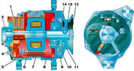
- G250P2 (Fig. 1) - alternating current with a built-in rectifier unit VBG-1 (or PBV-4-45), working together with a voltage regulator.
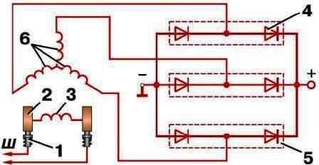
The electrical circuit of the generator is shown in fig. 2.
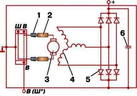
Fig. 3. Electrical diagram of generators 665.3701-01, 161.3771
-665.3701-01 or 161.3771 - AC with built-in integrated voltage regulators.
The electrical circuit of the generators is shown in fig. 3.
The generator is mounted on a bracket to the engine block on the right side.
The generator is driven by a V-belt from the crankshaft pulley.
G250P2 generator technical data
Direction of rotation (drive side) clockwise
Voltage (nominal), V 14
Rated current, A 28
Maximum current, A 40±5
The frequency of rotation of the generator shaft, at which the voltage at the terminals is 12.5 V at an ambient and generator temperature of 20 ° C, min -1:
- - at current equal to zero 900
- - at load current 28 A 2100
Number of stator phases (star connected) 3
Number of coils in phase 6
Number of stator coils 18
Number of turns in the stator coil 13
Stator winding - PEV-2 wire, F 1.35–1.46 mm
Excitation coil ..... PEV wire, F 0.74–0.83 mm
Number of turns per coil 490±10
Resistance of the excitation winding at 20° С, Ohm 3.7±0.2
Excitation winding current, A, no more than 3.05±0.2
Brush type M1
The force of pressing the springs on the brushes, gf 180–260
Ball bearings:
- - in the front cover 180603–KS9'
- - in the back cover 180502–KS9SH
Number of rectifier diodes 6
Permissible current for each diode, A 10
Permissible voltage drop at a current of 10 A, V, no more than 1
Technical data of generators 665.3701–01, 161.3771
Direction of rotation (drive end) clockwise
Voltage (nominal), V 14
Maximum current, A, not less than 55 (57)
Adjustable voltage at an ambient temperature of 25±10°C, a rotor speed of 3500 min -1 and a load current of 20A when operating with the battery on, V:
- - for "U-KhL" version 13.9–14.6
- - for execution Т.....13.4–14.1
Regulated voltage at ambient temperature from -25°C to +70°C with current change from 5A to 40A and rotor speed from 3000 min -1 to 8000 min -1 , B:
- - for "U-KhL" version 13.6–14.8
- - for version T 12.9–14.8
Start inspecting the generator with the brushes, brush holder and slip rings.
Make sure that the brushes are intact, do not stick in the brush holders and are in good contact with the slip rings; check the tension of the brush springs.
Replace brushes worn to a height of 8 mm (for generator brushes 665.3701-01 - 5 mm).
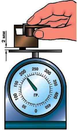
Measure the pressing force of the brushes (Fig. 4) against the slip rings with a dynamometer.
To measure the force, remove the brush holder, remove one brush, place the cover on the brush holder, holding it with your hand.
Then, with the end of the brush protruding from the brush holder, press on the cup of the switch balance.
When the brush protrudes 2 mm from the brush holder, measure the scale reading.
The force of pressing the springs on the brushes should be 180–260 gf.
Space Generator blow with air.
Wipe the brush holder, brushes and slightly dirty slip rings with a clean cloth lightly dampened with gasoline.
Smooth heavily soiled slip rings with slight burning and small roughness (removing the brush holder) with glass paper, grit 80 or 100, turning the rotor by hand.
Do not use sandpaper for this.
Worn, burnt, or with increased runout, grind the contact rings of the generator on a lathe and clean thoroughly.
Periodically remove the generator from the car to disassemble and clean it from dirt and dust.
Inspect all details carefully.
Check the pressure of the brushes.
The brushes must not jam in the brush holders. Replace worn bearings.
The "minus" of the battery should always be connected to the "mass", and the "plus" - connected to the "plus" terminal of the generator.
Inadvertently reconnecting the battery will immediately cause increased current through the generator diodes and they will fail.
It is not allowed to operate the generator with consumer wires disconnected from the “plus” terminal (especially with a disconnected battery).
This causes a dangerous rise in voltage, damaging the diodes and the voltage regulator.
It is not necessary to check the performance of the generator “for a spark”, even by briefly connecting the “plus” clamp of the generator to the “ground”. In this case, a significant current passes through the diodes and they are damaged.
You can only check the generator with an ammeter and a voltmeter.