")
")
")
")
")
")
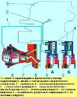
K-151, K-151D carburetors are installed on engines of model 402 and 4021.
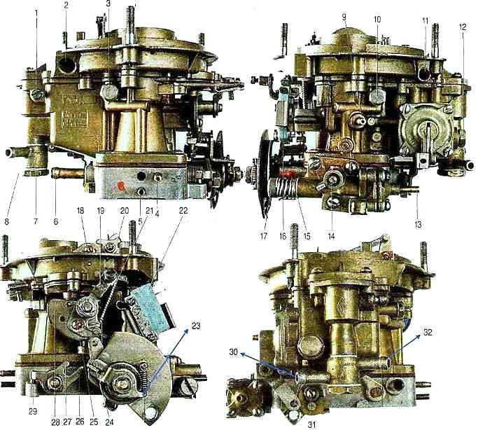
The K-151 carburetor (Fig. 1) consists of three main detachable parts connected through sealing gaskets with screws
Upper part - carburetor cover includes an air pipe, divided into two channels, with an air damper in the channel of the first chamber.
The middle part consists of a float and two mixing chambers and is the carburetor body.
The lower part - the throttle body includes mixing pipes with throttle valves of the first and second chambers of the carburetor.
The gasket between the middle and lower parts of the carburetor is sealing and heat-insulating.
Structurally, the carburetor consists of two mixing chambers - the first and second.
Each of the carburetor chambers has its own main dosing system.

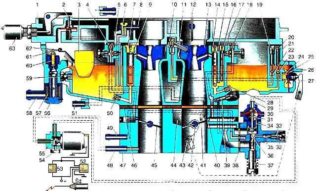
Scheme of K-151 carburetors. K-151 D: I - forced idle economizer control circuit (K-151 for ZMZ-4025, -4026); II - control circuit of the forced idle economizer (K-151 D for ZMZ-4061.4063); 1 - fuel valve; 2 - float 3 - plug; 4 - air jet of the transition system; 5 - emulsion nozzle of the transition system; 6 - screw for fastening the atomizer of the econostat of the second chamber; 7 - econostat atomizer of the second chamber; 8 - air jet of the main dosing system of the second chamber; 9 - emulsion tube of the main dosing system of the second chamber; 10 - small diffuser of the second chamber; 11 - exhaust ball valve of the accelerator pump; 12 - accelerator pump sprayer; 13 - air damper; 14 - small diffuser of the first chamber; 15 - air jet of the main dosing system of the first chamber; 16 - emulsion tube of the main dosing system of the first chamber; 17 - air jet block with emulsion tube of the idle system; 18 - emulsion jet of the idle system; 19 - air jet of the idle system; 20 - screw for factory adjustment of the mixture composition; 21 - main fuel jet of the first chamber; 22 - plug; 23 - carburetor cover; 24 - adjusting screw for bypassing fuel of the accelerator pump system; 25 - displacer; 26 - carburetor body; 27 - inlet ball valve of the accelerator pump; 28 - accelerator pump cover; 29 - spring; 30-lever drive accelerator pump; 31 - accelerator pump diaphragm; 32 - solenoid valve; 33 - electronic control unit; 34 - controller; 35 - microswitch; 36 - bypass jet of the accelerator pump; 37 - forced idle economizer diaphragm; 38 - forced idle economizer valve; 39 - restrictive cap; 40 - mixture composition screw; 41 - forced idle economizer housing; 42 - screw for idle adjustment; 43 - tube to the vacuum corrector; 44 - throttle valve of the first chamber; 45 - accelerator pump lever drive cam; 46 - accelerator pump lever roller; 47 - throttle body; 48 - throttle valve of the second chamber; 49 - vacuum supply tube to the solenoid valve; 50 - calibrated hole; 51 - gasket; 52 - main fuel jet of the second chamber; 53 - tube to the valve of the exhaust gas recirculation system; 54 - pipe for supplying crankcase gases; 55 - fuel supply pipe; 56 - drain tube; 57 - fuel filter
Idle system - with quantitative adjustment of constant mixture composition (autonomous idling system).
In the second chamber of the carburetor there is a transitional system powered by fuel directly from the float chamber, which comes into operation at the moment the throttle valve of the second chamber is opened.
Accelerator pump - diaphragm type.
An ecostat is provided in the second chamber to enrich the combustible mixture at full load.
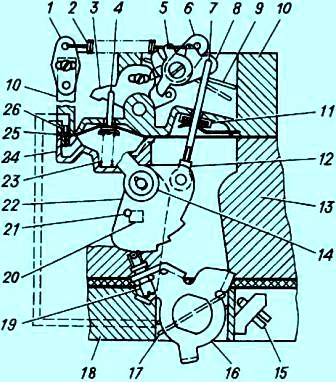
Scheme of a semi-automatic device for starting and warming up: 1,5,6,16 - levers; 2 - starting spring; 3 - intermediate lever; 4 - thrust of the pneumatic corrector; 7 - thrust; 8 - sector lever; 9 - air damper; 10 - carburetor cover; 11 - sealing element; 12 - adjusting clutch; 13 - body of the float chamber; 14 - air damper drive lever; 15 - thrust screw throttle primary section of the carburetor; 17 - throttle valve of the primary section of the carburetor; 18 - case of mixing chambers; 19 - screw with a roller; 20 - emphasis; 21 - pin; 22 - profile lever; 23 - pneumatic corrector spring; 24 - pneumatic corrector cover
Cold engine start system (Fig. 2) is a semi-automatic type, consists of a pneumatic corrector, a system of levers and an air damper, which is closed by the driver using a manual drive before starting a cold engine.
At the moment the engine is started, the pneumatic corrector, using the vacuum that occurs under the carburetor, automatically opens the air damper to the required angle, ensuring stable operation of the engine when warmed up.
When pulling the choke lever, you must press the accelerator pedal.
The fuel cut-off system (forced idle economizer) comes into operation in the forced idle mode when the vehicle is braked by the engine, when there is no need to supply fuel to the engine.
This ensures fuel economy and reduces the emission of toxic substances into the atmosphere.
The system for shutting off the fuel supply of the K-151 carburetor consists of a control unit 33 (see Fig. 1), a microswitch 35 of the solenoid valve 32 and a forced idle economizer.
The microswitch and forced idle economizer are located on the carburetor, the solenoid valve - the control unit - on the front panel of the cab.
Control unit 33 is a device that, depending on the frequency of electrical impulses coming from the ignition coil, controls the solenoid valve 32.
When the accelerator pedal is released, the contacts of the microswitch 35 must be open.
The fuel cut-off system works as follows
When the accelerator pedal is released and the engine speed is more than 1400 min -1, the control unit does not supply voltage to the solenoid valve, as a result of which atmospheric air enters the forced idle economizer through the channels of the solenoid valve, the valve of which closes the idle channel.
In the event of a malfunction of the fuel cut-off system (the engine does not start or “stalls” when the throttle pedal is released), you must first make sure that the electrical contacts of the system elements are reliable, after which you should sequentially check the operation of the solenoid valve, microswitch and control unit .