")
")
")
")
")
")
You will need: 12" wrench and socket, 17" wrench, 6" hex wrench
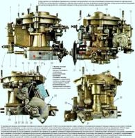
Two camshafts are installed in the cylinder head: on the right - for intake valves, on the left - for exhaust valves.
Disconnect the wire from the negative terminal of the battery.
Remove the cylinder head cover.
Remove the front cover of the cylinder head (see Replacing the cylinder head cover gasket ZMZ-409).
Set the piston of the 1st cylinder to TDC of the compression stroke.
Remove the upper chain tensioner.

Remove the two bolts securing the top chain guide and remove the chain guide.

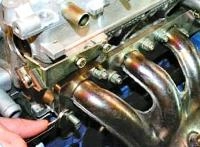
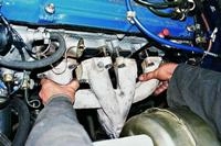
Remove the bolts securing the camshaft sprockets, holding the shafts from turning with a square wrench.

Lifting the chain, remove the sprockets from the intake and exhaust camshaft journals.
If the sprockets are tight on the camshafts, remove them with a puller.

Lock the chain under tension.

Remove the camshaft bearing cap bolts two or three turns, then another two or three turns.
Remove the bolts in this order until the valve springs are fully decompressed.

Remove the front bearing cover and remove the plastic thrust washers

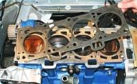
Remove the remaining bearing caps and remove the camshafts from the cylinder head bearings.
After removing, wash all parts with gasoline, wipe and dry.
Inspect the camshafts. If scuffs, shells, cracks are found on the necks and cams, replace the shafts.
Measure the diameter of the camshaft journals.
The nominal diameter of the first neck (closest to the sprocket) is 42.0 + 0.050 -0.075 mm, the maximum allowable diameter is 41.9 mm.
The nominal diameter of the remaining journals is 35 + 0.050 -0.075 mm, the maximum allowable diameter is 34.9 mm.
If the diameter of at least one journal is less than the limit, replace the camshaft.
Measure the height of the cams.
The nominal height of the cam is (46.0±0.25) mm, the maximum allowable height is 45.5 mm.
If the height of at least one cam is less than the limit, replace the camshaft.
Remove small scratches on the necks and cams by grinding, and then polish the necks and cams.
Install the camshaft on two prisms and measure the runout on the middle neck with an indicator.
Nominal runout 0.025 mm, maximum allowable runout 0.04 mm. If the runout is greater, replace the camshaft.
Check the clearances in the camshaft bearings.
To do this, you need to put a cylindrical mandrel di 35.0–0.02 mm diameter for centering the lid.
Install the camshaft cover, tighten the cover bolts to 19–23 Nm (1.9–2.3 kgf m).
Remove the drift towards the rear end of the cylinder head.
Measure the inner diameter of the camshaft bearing and calculate the gap as the difference between the diameter of the bearing and the diameter of the corresponding camshaft journal.
The maximum allowable gap is 0.15 mm.
If the clearance in at least one camshaft bearing is greater than the allowable value, replace the shaft or cylinder head.
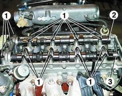
The camshaft covers are machined complete with the block head, so they cannot be interchanged.
Each lid has a serial number engraved on it.
The numbering of the covers starts from the front support (closest to the gear) of the intake camshaft.
Next, the exhaust camshaft caps are numbered on the camshaft gear side.
A phase sensor plate is installed at the rear end of the exhaust camshaft.
Lubricate the journals and cams of the camshafts and bearings in the cylinder head with clean engine oil.
Lay the camshafts in the cylinder head: the intake camshaft with the sprocket pin up, the exhaust camshaft with the pin to the right.
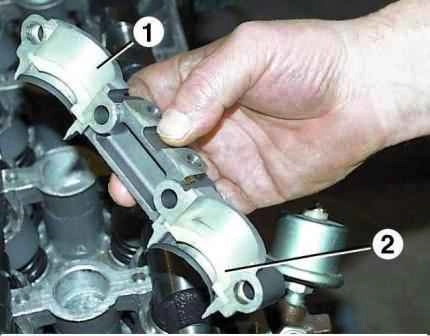
Lubricate the front cover 1 of the camshafts with the thrust half rings 2 installed in it with clean engine oil.
Install cover 1 on the guide bushings in the camshaft bearings.
In this case, half rings 2 must enter the grooves on the camshafts.
Lubricate caps #3 and #7 with clean engine oil and install them on the guide bushings in the camshaft bearings.
Turn the bolts of the covers until the covers come into contact with the supports.
Lubricate the rest of the camshaft covers with clean engine oil and reinstall them.
Turn the bolts of the covers until the covers come into contact with the supports.
Tighten the camshaft cap bolts to 19–23 Nm (1.9–2.3 kgf m).

Check for ease of rotation of the camshafts.
To do this, turn each shaft with a wrench by the square on the shaft so that the valve springs of any cylinder are completely compressed (the cams of the shaft are directed downwards).
Turn the camshaft slightly again, it should turn further under the action of the valve springs until the next cams come into contact with the valve lifters.
Turn the camshafts so that the alignment pins of the sprockets are horizontal and directed in different directions (the position of the camshafts corresponds to the position of the piston of the 1st cylinder at TDC).
Put on the camshaft drive chain (see Replacing the chains and gears of the UAZ Patriot gas distribution mechanism).
Install the hydraulic chain tensioner, see Removal and installation of UAZ Patriot hydraulic chain tensioners.
Install all removed parts in the reverse order of removal.